
|

|
Forum Index : Microcontroller and PC projects : PicoMite: PicoGAME VGA development
| Author | Message | ||||
| Mixtel90 Guru Joined: 05/10/2019 Location: United KingdomPosts: 6814 |
Standard joystick inputs are pull-down so are connected with the common to GND (8) and the switches to the joystick input pins 1,2,3,4 (Up,Down,Left,Right). FIRE is connected to pin 6. Pin 7 is a 3V3 supply to power joysticks that have auto-fire and other strange additions. It may or may not work with sticks that are expecting 5V. Have fun. :) Mick Zilog Inside! nascom.info for Nascom & Gemini Preliminary MMBasic docs & my PCB designs |
||||
| Martin H. Guru Joined: 04/06/2022 Location: GermanyPosts: 1115 |
Thank you Mick for the clarification. The more I googled, the more unclear it became, since both variants would be possible. 'no comment |
||||
| thwill Guru Joined: 16/09/2019 Location: United KingdomPosts: 4047 |
Note that as I understand it the PicoGAME doesn't provide any "standard" for the "Atari" joystick having a second (or more) fire button. If you're building a custom (digital) joystick for the PicoGAME (and its purpose is not to test the "Atari" joystick support) then it may make more sense to hide a 4021 shift register and a bunch of 10K resistors inside it and wire it up as an NES controller. Best wishes, Tom Edited 2022-08-04 22:18 by thwill Game*Mite, CMM2 Welcome Tape, Creaky old text adventures |
||||
| Mixtel90 Guru Joined: 05/10/2019 Location: United KingdomPosts: 6814 |
Normally a second button would be on pin 9 for an Atari ST or Commodore joystick. In fact, a Commodore stick can also use pin 5 for button 3. I like the idea of converting a mechanical stick to a NES controller. :) You are some buttons short to use it properly though. Mick Zilog Inside! nascom.info for Nascom & Gemini Preliminary MMBasic docs & my PCB designs |
||||
| Martin H. Guru Joined: 04/06/2022 Location: GermanyPosts: 1115 |
in those days, we just had one Firebotton and this was enough.. As far as i remeber, ff the Joystick had two buttons (Quickshot 1 or Kompetition Pro ), they were connected in parallel just for left/right handed use. On my selfmade Joystick,for all eventualities, I connected the 2nd fire button to pin 9 Edited 2022-08-04 23:06 by Martin H. 'no comment |
||||
| Volhout Guru Joined: 05/03/2018 Location: NetherlandsPosts: 4256 |
Chinese game controllers.... I received 2 samples from Tom (thwill) and have tried to modify the PIONES PIO state machines to support them, and map the keys to the correct values. In doing so I discovered an essential difference between the Chinese controller and the 4021 handwired NES controller. When clocked with more than 8 bits the handwired controller outputs 0's for the surplus bits, where the Chinese controller outputs 1's. So clocked with 32 bits, no key pressed, the 4021 controller outputs 0x000000FF The Chinese controller outputs 0xFFFFFFFF After inversion of the bits (the switches are active low) the 4021 handwired controller has 0xFFFFFFxx The chineese NES controller has 0x000000xx I looks like the Chinese controller uses a 4021 (alike) chip with pin 11 (shift IN pin) tied to Vcc in stead of ground, which is essentially better since it makes a better compatibility between NES and SNES controllers (the homes build NES controller in a SNES machine would seem to have the extra buttons pressed all the time). According Toms documentation there is another mismatch between the NES and SNES data. The A, B and Y button do not show up on the same bits. Anyway, here is some PIO code to test different controllers on. The PIO generates 32 clocks, since that is the easiest way to get the data at the correct bits in the output value, and also support SNES. When this works I could massage it into better documented (final) version. But looking at the MMbasic equivalent Tom made (simple and easy to understand), using the (for most people abracadabra) PIO may not be the best solution for game development. 'PIONES32 - PIO SPI for SNES controller 'VGApicomiteGAME board revision 1.4 'Shrink version (both stamemachines run same code) '-------------------------------- IO pin configuration ----------------------- - 'pin asignment K8/sm0 K7/sm1 'data (in) gp1 gp4 'latch (out) gp2 gp5 'clk (out) gp3 gp22 'reserve pins for PIO1 sm0 SetPin gp1,pio1:SetPin gp2,pio1:SetPin gp3,pio1 'sm0 SetPin gp4,pio1:SetPin gp5,pio1:SetPin gp22,pio1 'sm1 'power the 2 ports K8 and K7 if needed SetPin gp14,dout:Pin(gp14)=1 SetPin gp15,dout:Pin(gp15)=1 '--------------------------------- PIO configuration -------------------------- 'PIO1 execute frequency f=200000 '200kHz to achieve same responsiveness as 100kHz 8 bit controller 'note: the PIO program for both PIO's is the same, only the IO definition 'in the pinctrl register is different. The statemachines actually run same code 's=2^19 'default with IN shift left, OUT shift right s=2^19+2^18 'default with IN OUT shift right 'pio config PIO1 sm0 p0=Pio(pinctrl 1,1,1,GP1,GP3,GP2,GP3) 'GP1=IN base GP2=SET GP3=OUT/SIDESET 'pio config PIO1 sm1 p1=Pio(pinctrl 1,1,1,GP4,GP22,GP5,GP22) 'GP4=IN base, GP5=SET GP22=OUT/SIDESET '------------------------------ PIO program (comment) ------------------------- 'pio1 sm0 program, identical code for sm0 and sm1, clock is side set pin 'adr/instr/comment '0 E081 'set pindir latch, out [side 0] '1 E000 'set latch low [side 0] '2 A0EB 'MOV null inverted to OSR [side 0] '3 6081 'OUT 1 bit OSR to pindirs [side 0] set clock output '4 E001 'latch high [side 0] latch pulse '5 E000 'latch low [side 0] '6 E02F 'load X with value 15 [side 0] <--change no of bits to 7/15/31 '7 A0C3 'mov NULL to ISR [side 0] '8 4001 'shift 1 bit data in ISR [side 0] '9 1048 'JMP X-- to &h8 [side 1] this is the clock pulse 'A A0CE 'invert ISR [side 0] to get correct key value 'B 8000 'push ISR [side 0] 16 bits to fifo 'C 0004 'jmp to &h4 [side 0] next cycle '&h0D....&h1F not used '------------------------- END PIO program (comment) -------------------------- 'pio1 program in data statements '8bit 'Dim a%(7)=(&h6081A0EBE000E081,&hA0C3E027E000E001,&h0004800010484001,0,0,0,0,0) '16 bit 'Dim a%(7)=(&h6081A0EBE000E081,&hA0C3E02FE000E001,&h0004800010484001,0,0,0,0,0) '32 bit 'Dim a%(7)=(&h6081A0EBE000E081,&hA0C3E03FE000E001,&h0004800010484001,0,0,0,0,0) '32 bit inverted Dim a%(7)=(&h6081A0EBE000E081,&hA0C3E03FE000E001,&h8000A0CE10484001,4,0,0,0,0) 'program and start the PIO1 state machines PIO program 1,a%() 'program PIO1 PIO init machine 1,0,f,p0,,s,0 'init sm0 from address &h00 PIO init machine 1,1,f,p1,,s,0 'init sm1 from address &h00 (same code) PIO start 1,0 'start PIO1 sm0 PIO start 1,1 'start PIO1 sm1 '------------------------------ MAIN level ----------------------------------- Print "running" Dim h%(4) 'read the FIFO's that contain the NES controller keys Do PIO read 1,0,5,h%() 'read from FIFO sm0 Print @(0,40) Hex$(h%(4)), 'print value PIO read 1,1,5,h%() 'read from FIFO sm1 Print @(100,40) Hex$(h%(4)) 'print value Pause 200 Print @(0,40) Space$(32) Loop 'While Inkey$="" End Edited 2022-08-11 15:32 by Volhout PicomiteVGA PETSCII ROBOTS |
||||
| Mixtel90 Guru Joined: 05/10/2019 Location: United KingdomPosts: 6814 |
That's very interesting! Thanks. I wonder if the change to the shift register input (and probably the swapped buttons) was a mistake in copying an original controller or a deliberate ploy by Nintendo to prevent the use of a "wrong" (i.e. cheaper or cloned) controller? Not something we're likely to ever find out. The beauty of Tom's MMBasic code is that it's user "fixable" to suit whatever controller is used. That would be much harder to do with the PIO, I think. Mick Zilog Inside! nascom.info for Nascom & Gemini Preliminary MMBasic docs & my PCB designs |
||||
| thwill Guru Joined: 16/09/2019 Location: United KingdomPosts: 4047 |
Thanks @Volhout, Does any of this explain why for the standard NES behaviour on those controllers it is necessary to pulse the clock after reading bit 7 and before pulsing the latch ? That's not as nuts/inconvenient as it might seem: 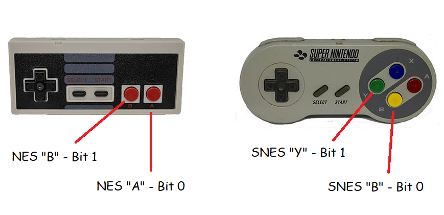 Note that Y & B on the NES are positioned similarly to B & A on the NES controller. As a right-hander NES/A and SNES/B are comfortably the primary fire buttons and NES/B and SNES/Y the secondary fire buttons - I suspect the fact that they set (actually clear) the same bit is a piece of considered design by Nintendo. That's my feeling too, especially since with every controller I've tested you only need a 1 microsecond latch/clock pulse rather than the 12 microseconds that the real NES hardware apparently used. Nevertheless thank you for your efforts @Volhout, hopefully the controllers I sent are some recompense. As above I think it was a well considered decision and not even a nuisance for us except with regards play documentation. It's interesting that Nintendo didn't try and lock out 3rd party controllers (they went to considerable effort with regards 3rd party cartridges). Note also that the real NES and SNES have 7-pin connectors (different from each other) and not the DE-9/DB-9 the clones and the PicoGAME use. Sorting out the controller support, especially for driving game menus and entering names in the high-score table is actually proving more of a challenge than writing the rest of my (simple) game, but I think it is coming together and at the end of the day will be quite elegant - even if I do say so myself. Best wishes, Tom P.S. I have my inductors for the 2.0 PCB now, and half! of the acrylic enclosure from @bigmik has arrived, fingers crossed that the postie delivers the second half today so I can post some photos. Edited 2022-08-11 18:40 by thwill Game*Mite, CMM2 Welcome Tape, Creaky old text adventures |
||||
| Martin H. Guru Joined: 04/06/2022 Location: GermanyPosts: 1115 |
today it arrived from PCBWay 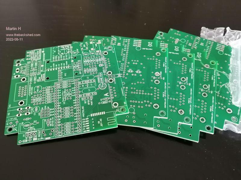 so, you got me  Total products amount (USD) $5.00 Total Freight cost (USD) $11.44 Bank fee (USD) $1.19 VAT fee (USD) $3.35 Total (USD) $20.98 EUR 20.37  todo: Resize the template for my 3D-printed "SNES Style" Case to fit the PCB in 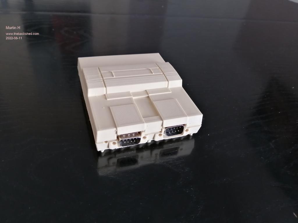 Edited 2022-08-11 20:14 by Martin H. 'no comment |
||||
| Volhout Guru Joined: 05/03/2018 Location: NetherlandsPosts: 4256 |
Hi Tom, No, the level at clock pulses 9...32 does not explain the strange behavior with the right arrow button. I have investigated a bit, and the behavior is indeed strange. The controller outputs first time a correct code 128, and successive codes are 129. This behavior is not seen at other keys. It is not depending on the clock edge, it is not depending on the Vcc (varied it over a wide range). It feels like a code fault in the controller chip. The 8'th clock cycle solves it...so I would leave it at that. Regards, Volhout PicomiteVGA PETSCII ROBOTS |
||||
| Sasquatch Guru Joined: 08/05/2020 Location: United StatesPosts: 362 |
Unicorns do exist! I bought a NES Clone 500 in 1 game at a Thrift Shop (Charity Shop, Opportunity Shop) for $12.99 USD. It came with two NES style controllers. These controllers have 9pin D plugs, do not exhibit the Right=129 issue, and the Dpads aren't wonky! 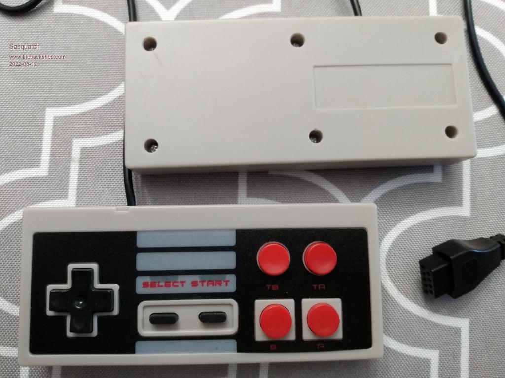 Unfortunately there are no identifying markings on either the controllers or the game console. Not even a date or "Made in Taiwan". The epoxy-blob PCB inside the controllers is labeled with "8bit-2" There are several characteristics that might help identify similar controllers: 1. The "center" 2 screws on the back are slightly offset. 2. There is a "notch" on the front bezel corresponding to the position of the connecting cable. 3. There are translucent areas just above the select and start labels, as though made for LEDs to shine through, but there are no LEDs inside. 4. The 2 rows of fire buttons are spaced farther apart and only the lower A and B buttons are outlined in gray plastic squares. 5. The select and start buttons are thin and black not gray. Unfortunately, a quick scan of AliExpress did not find an exact match. These controllers on AliExpress seem like the closest match I could find thus far: https://www.aliexpress.com/item/3256802078199613.html Please note that I have not purchased or tested the controllers from the above link. They are NOT an exact cosmetic match to the ones I have tested, they are just the closest match I was able to find quickly on AliExpress! I did order two of these: https://www.aliexpress.com/item/3256802759223064.html And two of these: https://www.aliexpress.com/item/2251832801091116.html I really like the shape and feel of the SNES controllers and I figure it should be easy enough to swap the cables. I'll let you know how it goes when they arrive in the next few days. Regards, Edited 2022-08-12 10:16 by Sasquatch -Carl |
||||
| thwill Guru Joined: 16/09/2019 Location: United KingdomPosts: 4047 |
Except that we both already know that there is not a 1:1 correspondence between the pictures (or descriptions) of these items and what you actually receive  . .Best wishes, Tom Game*Mite, CMM2 Welcome Tape, Creaky old text adventures |
||||
| thwill Guru Joined: 16/09/2019 Location: United KingdomPosts: 4047 |
@Sasquatch my "SNES gamepads" which I believe were ordered from the same listing as yours have arrived, and do not match the picture on the listing ROFLOL. 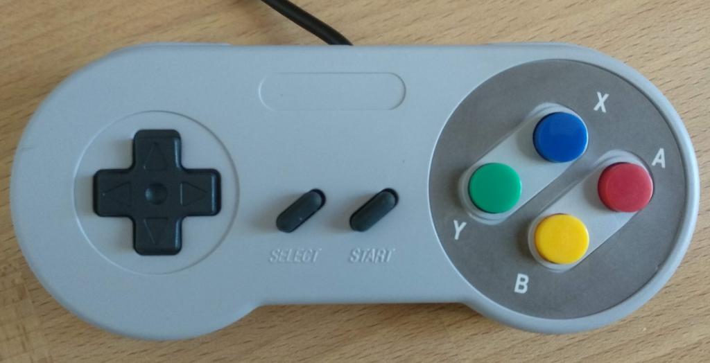 Whether it actually works will have to wait a few days until I find time to rewire it with a DB-9 instead of the bespoke 7 pin linear connector. In the meantime I've opened one up and it is interesting inside, there is a discrete 16-pin SMD IC (unmarked) rather than an epoxy blob, and that's not enough pins for a 16-bit shift register, though each button (except SELECT) is attached to its own pin so it isn't an NES gamepad in disguise either. There also aren't the 12 pull-up resistors you would expect. 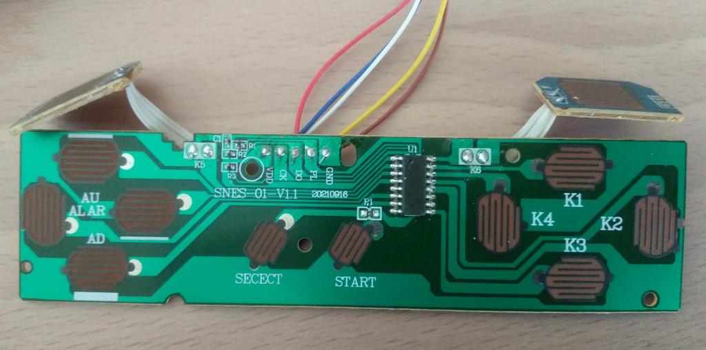 I guess it must be a micro-controller, but it seems to have VDD on pin 5 and GND on pin 12, that's unconventional isn't it ? Also if it is a micro-controller then is it probably a 5V one and thus unlikely to run off the PicoGAME's 3.3V controller supply line ? 16 pins isn't generally enough as you've got 12 controller buttons + LATCH, CLOCK, DATA, VCD and GND = 17, to overcome this SELECT appears to be connected to the same pin as the DATA line but via a 1K resistor ? Pin Function ================== 1 Left Bumper 2 Up 3 Right 4 Left 5 VDD 6 Down 7 Start 8 Clock 9 K3 10 Select/Data 11 Latch 12 Ground 13 K2 14 K4 15 K1 16 Right Bumper Best wishes, Tom Edited 2022-08-12 22:37 by thwill Game*Mite, CMM2 Welcome Tape, Creaky old text adventures |
||||
| Volhout Guru Joined: 05/03/2018 Location: NetherlandsPosts: 4256 |
It is a MCU, most likely a Holtek one. In the early days of the Microchip PIC microcontrollers Holtek made similar devices (copied ?) that where quite a bit cheaper (at that time $0.22 for a MCU, where a similar Microchip PIC16F84 was 2 dollar). And they had (at that time) faster chips. So a real thread for Microchip. This particular chip could be have been used (1k OTP memory, 8 bit core). 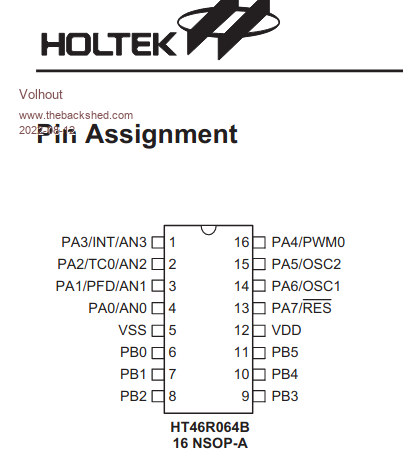 PicomiteVGA PETSCII ROBOTS |
||||
| thwill Guru Joined: 16/09/2019 Location: United KingdomPosts: 4047 |
Thanks @Volhout, though it looks like VDD and GND are the wrong way around for it to be that MCU unless I managed to massively confuse myself ... or the silkscreen on the board had them reversed ... that might make rewiring the connector fun. EDIT: ... no I and the silk screen have got it correct, GND is the massive track/plane and you can see clearly it is connected to pin 12. Best wishes, Tom Edited 2022-08-13 00:06 by thwill Game*Mite, CMM2 Welcome Tape, Creaky old text adventures |
||||
| Sasquatch Guru Joined: 08/05/2020 Location: United StatesPosts: 362 |
Hi @thwill, My AliExpress SNES controllers arrived today. I decided to do some testing before I swapped the cables. I can confirm that the ones I received have the same PCB and unmarked SMT chip as yours, and they don't match the previous 2 that I ordered about a year ago. Sigh.... First, I like the positive feel of the buttons and particularly the front bumper switches have a nice firm feel. Second, these things are S..L..O..W at least at 3.3V they are. I had to increase all the pulse duration and loop delays to get consistent results. This kinda makes sense if they are using a small 8 bit micro-controller as opposed to a shift register. It may actually work faster at 5V as it was probably designed for. Third, the "Select" button reports all zeros.(inverted to ones in software) It's pulling down the data output too low. I see there is a pull-up resistor on the Data Out and a resistor in series with the select button. This was also likely designed to work at 5V. Otherwise, the controllers seem to report all 12 bits correctly. I'd like to do some testing on these with a 5V power supply and check the timing with a O'Scope, but I would need to use a different test platform as the Pico pins aren't 5V tolerant. In summary, for use with the PicoGameVGA, I'm afraid these things are a BUST! -Carl |
||||
| thwill Guru Joined: 16/09/2019 Location: United KingdomPosts: 4047 |
Starting to get rather peeved about this, though I guess this one was never the ideal choice because the cable required hacking. I think @vegipete has ordered something, possibly the "not" SNES controller on my reluctant recommendation so I'll wait to see how that turns out before investing any further. I suppose I'm gathering material for a seriously nerdy YouTube video on these controllers ... but I'm not sure it is even useful information when you can't guarantee the vendors will send you the exact pictured item. Best wishes, Tom Game*Mite, CMM2 Welcome Tape, Creaky old text adventures |
||||
| phil99 Guru Joined: 11/02/2018 Location: AustraliaPosts: 2141 |
Would it be worth putting a level shifter in them (or in line to the plug)? If these controllers don't use pin 6 on the PicoGame then the two resistors and transistor that connect to that pin could be removed and a wire run from pin 6 to 5V to power it. If you need to retain compatibility with controllers that do use pin 6 external supply may be needed. Plan "B" for 5V, a boost converter. The very simple sort used in solar garden lights might work. Dirt cheap. Or the chips used to get 5V from a lithium cell would definitely work. Edited 2022-08-13 10:40 by phil99 |
||||
| Volhout Guru Joined: 05/03/2018 Location: NetherlandsPosts: 4256 |
Thanks for reminding me Sasquatch.. The NES controlllers I received from Tom work correctly with a pulse duration of 1us (0.001) up to 1ms (1). Outside this window they start to make errors of respond with 0xFF (255). And they work fine with PIONES(8/16/32). So they are usable for the VGApicoGAME platform (1.4). Regards, Volhout Edited 2022-08-13 15:33 by Volhout PicomiteVGA PETSCII ROBOTS |
||||
| Mixtel90 Guru Joined: 05/10/2019 Location: United KingdomPosts: 6814 |
Phil: You can set GP14 (or GP15) high to allow the controller to draw more current. That might help. It's still 3V3 though. We have to be careful as any on-board level shifting would have to be on all the pins, including GP28 as this is used as a digital pin, unfortunately it is also used as an ADC pin. An external adapter might be simpler to implement but getting 5V out of the DB9 is fraught with difficulties! Perhaps I should have stuck with the Nunchucks, but I was led away from the paths of righteousness. ;) Mind you, there are no PCB sockets available for those anyway and you have to rely on tinned PCB. Not ideal. Edited 2022-08-13 18:20 by Mixtel90 Mick Zilog Inside! nascom.info for Nascom & Gemini Preliminary MMBasic docs & my PCB designs |
||||