
|

|
Forum Index : Solar : Deciding if I should build this solar heater
| Author | Message | ||||
| rogerdw Guru Joined: 22/10/2019 Location: AustraliaPosts: 852 |
Haha ... all those years of trying to teach conservation and power saving has finally kicked in ... probably think they're doing you a favour ... silly old Dave forgot to turn off the heater, I'll do him a favour.  I had all intentions of running some tests ... but have got a bit lazy. I set up two identical sets of three tubes and fans ... and was going to try some side by side comparisons ... but they're still sitting there. Maybe it's time to do them. Haha, yeah now you put it that way. Good point, that is exactly right ... and we'll usually only need the fan when the sun is shining, so should be easy enough. Nuthin wrong with setting the bar high ... make a great youtube title with some unbelievable (but truthful) COP figures. Quite likely, but that's why I need to understand some of the numbers. eg. my existing small 6" blauberg fan is ~50 watts and moves 500 cubic metres/hr with max pressure of 50 Pa This fan here can move 3,434 cubic metres/hr at 633 Pa ... ... using 36-56V DC 5.8 A 278 Watts So, 6.8 times more volume ... 12.6 times more pressure ... 5.5 times more power No definitely not. He hasn't rung back yet but he works for a pretty big crowd so should have access to a lot of gear. Can't wait to have a yack with him. Yes, agreed ... the tubes are definitely the bottleneck ... and not just because they are the smallest cross secional area ... but because of the fairly narrow airchannels and the u-turn for the air, compared to all the other ducting which is wide open. I was originally planning on inline fans in the ducts in the ceiling ... but now I'm leaning towards a fan at the end of the main duct out on the roof. Should be able to make up a housing that fits in with the unit and at least be fairly easy to get at ... even if it is out in the weather. And I do like the idea of a filter as well ... would be an absolute pain having to dismantle the thing every couple years to clean it all out with a bottle brush ... no thanks.  When you suggest the developed pressure is not all that high, typically 1,000 pascals ... that's still 20 times higher than my existing fan. Do you think it needs to be that much more? I've looked up how to make a manometer ... how do you attach it in my case ... does the end of the duct have to be blocked so the pressure can act on the end of the tube? ... or how/what? Thanks again for all the input guys, I'm having trouble keeping up.  Cheers, Roger |
||||
| rogerdw Guru Joined: 22/10/2019 Location: AustraliaPosts: 852 |
Todays results seemed a bit unusual ... and with the cloud we had I was surprised to see the fan run at all ... let alone cycle on and off all day. 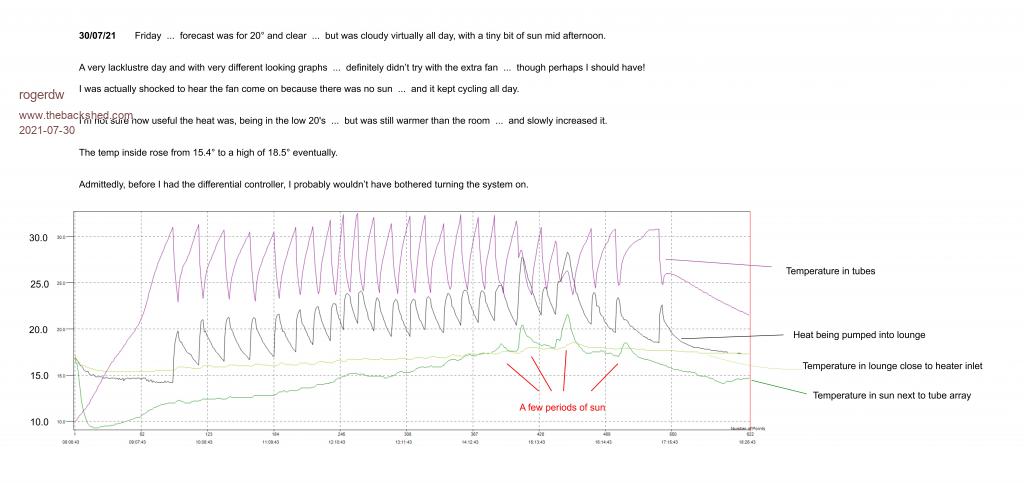 Cheers, Roger |
||||
| rogerdw Guru Joined: 22/10/2019 Location: AustraliaPosts: 852 |
Tony, you suggested the other day that I should look at it as trying to cool down the tubes ... not so much about warming the house. Taking a step back and thinking about that ... the first thing that comes to mind is that the tube needs internal fins, pressed against the glass ... ... just like we'd fit a heatsink on the back of a transistor to get the heat off it. I can picture having some copper foil concertina'd up, rolled up and slid inside. Doesn't sound too easy to do on a large scale ... plus would reduce airflow because of more restriction. Of course using water would have been the most obvious ... haha!!! Cheers, Roger |
||||
| Warpspeed Guru Joined: 09/08/2007 Location: AustraliaPosts: 4406 |
The control system is working great, there may not have been much sun, but you still gained about four degrees in the lounge throughout the day. Its very difficult trying to guess what your back pressure is likely to be, or what may be required. "High" is a relative term. An actual measurement would help a great deal. A water manometer is a very easy thing to make. All you need is some clear plastic tube with some water trapped in it. Any difference in air pressure forces the water to rise and fall. Pressure is measured in "inches of water" the difference in heights between the two columns. In fact it's the most accurate way to measure very low pressures. 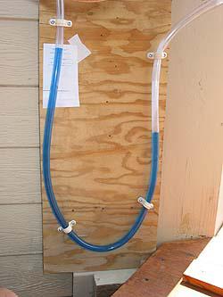 Just drill suitable holes in your two manifolds, and insert the ends of your plastic tube, its as simple as that. The other thing we need to know is the CFM airflow that corresponds to that pressure measurement. With those two figures we can then come up with a reasonable blower requirement for your big system. Edited 2021-07-31 08:43 by Warpspeed Cheers, Tony. |
||||
| rogerdw Guru Joined: 22/10/2019 Location: AustraliaPosts: 852 |
Yes, I was surprised to see any activity at all, so have to be happy with the results. Wasn't expecting much from today either due to the forecast ... cloud, rain, 90% chance of 5-20mm ... yet the sun is out and we've had half a dozen cycles already. I watched a few youtube videos yesterday to get the concept, so that's under control ... but the holes we want are so we can measure the pressure near the start of the duct and also one near the end? ... or between the start and the end? Ok, my anemometer can give readings in CFM, so I can note those as well. Cheers, Roger |
||||
| Warpspeed Guru Joined: 09/08/2007 Location: AustraliaPosts: 4406 |
There should not be much pressure drop in the manifold, so anywhere along the manifold should be fine. Your airflow meter will only read directly in CFM if all the air flows through the airflow meter impeller, and that may greatly restrict airflow and skew the results. A better way is to measure air velocity coming out of the duct in feet per minute, then calculate CFM by multiplying that by the flow area of the duct in square feet. That way the flow meter itself adds no additional restriction. Cheers, Tony. |
||||
| rogerdw Guru Joined: 22/10/2019 Location: AustraliaPosts: 852 |
Thanks ... so one end of the tube open to atmosphere and other end into manifold. With the meter I can load in the cross sectional area of the duct so it reads out directly in CFM or CMM or CMS ... though the area input in square metres is only accurate to 3 decimal places ... so may be better to do it manually. Cheers, Roger |
||||
| Warpspeed Guru Joined: 09/08/2007 Location: AustraliaPosts: 4406 |
I would not stress yourself out about extreme accuracy Roger. Just ball park readings will be fine. I did quite a bit of blower testing a few years ago myself, and here is a thread on the PTS airflow bench Forum. I post over there as "Tony" but my signature there also includes my Warpspeed identity. The facts and figures I mention there should work just as well for us here too, its very easy to extrapolate flows and pressures and drive power. Even had a go at building a crude experimental blower housing out of an old oil drum which worked just as well as an expensive sexy commercial scroll housing. http://www.flowbenchtech.com/forum/viewtopic.php?f=15&t=1188 Cheers, Tony. |
||||
| rogerdw Guru Joined: 22/10/2019 Location: AustraliaPosts: 852 |
Okay, well so far today the rain has held off so I've managed a few tests. Thanks for the help Tony, not surprised to see you know your fans too. First, the outlet duct has an internal cross sectional area of .1726 square feet. -------------------------------- By itself - the original 6" fan on High Speed (Specs. 50W - 560 cubic mtr/hr) Inlet Manifold = 5/8" Outlet Manifold = 3/16" Outlet Air Velocity = 14.0 ft/s -------------------------------- Added 8" fan (on Low) blowing into inlet manifold ... assisting 6" fan (Specs. Low 76W - 805 cubic mtr/hr) Inlet Manifold = 1-1/8" (one and one eighth inch) Outlet Manifold = 7/16" Outlet Air Velocity = 19.0 ft/s -------------------------------- 8" fan (on High) blowing into inlet manifold ... assisting 6" fan (Specs. High 108W - 1080 cubic mtr/hr) Inlet Manifold = 1-5/16" (one and five sixteenths inch) Outlet Manifold = 3/8" Outlet Air Velocity = 19.35 ft/s Cheers, Roger |
||||
| rogerdw Guru Joined: 22/10/2019 Location: AustraliaPosts: 852 |
31/07/21 Saturday ... forecast was for 20 degrees, cloudy and rain ... with 90% chance of 5 - 10 mm of rain. The day started off pretty well with sunshine even earlier than usual with fan first turning on a couple minutes after 8. It came and went for a while and eventually came out properly around 10:30 for an hour and again for a while from about 13:30. The promised rain started about 14:30 and it's been pretty grey since then. The temp inside rose from 16.5 to a high of 20.6 I spent some time just before midday taking pressure and airflow velocity readings ... so I stopped and started the fans a few times out of the normal sequence. Hopefully the readings will allow Tony to guide me on which way to go with the new machine. It seems to me that the extra airflow through the system is extracting more heat from the tubes than normal ... and a couple times I thought that the fan turned off before it was necessary. I finally woke up to the fact that the Ld was set to turn off when the outlet temp got to within 10 degrees of the room temp ... I though I had it set to 5 degrees. Rather than make too big a jump, I changed it to 8 degrees and will watch how that affects things. 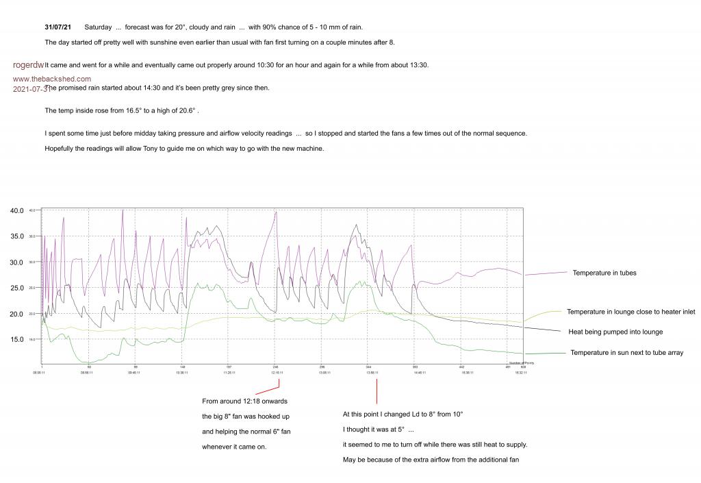 Cheers, Roger |
||||
| Warpspeed Guru Joined: 09/08/2007 Location: AustraliaPosts: 4406 |
Hi Roger, I have been away most of the day but have just now returned. O/k those figures are extremely helpful. First looking at just the small 6" blower running at high speed. Inlet manifold 0.625 inches Outlet manifold 0.1875 inches Pressure difference 0.4375 inches. Output velocity 14 ft/sec multiplied by 0.1726 square feet = 2.4164 cubic feet/sec or 144.98 CFM. The blower is rated at 560 cubic metres per hour (open flow) x 35.31 = 329.56 CFM. So 0.4375 inches of back pressure reduces our flow from 329 CFM to 145 CFM about roughly half. That is probably a pretty fair match between blower capacity and flow resistance, but two things stand out. Our total airflow of 145 CFM is not really sufficient to pull all of the available heat from the tubes, the tubes still get pretty hot with the blower running continuously even on a cloudy day. The second observation is that 0.4 inches is a pitifully low back pressure, but it is high enough to really challenge the flow capacity of that axial fan. *************************************** Now when you hook up the big 8" guy on slow speed to the small 6" guy, we get: Inlet manifold 1.125 inches Outlet manifold 0.4375 inches Pressure difference 0.6875 inches. Output velocity 19 feet/sec multiplied by 0.1726 square feet = 3.279 cubic feet/sec or 196.8 CFM. The blower is rated at 805 cubic metres per hour (open flow) x 35.31 = 28,424 cubic feet per hour or 473.7 CFM. The big blower is being substantially blocked by back pressure, 473 CFM drops to 197 CFM. Even on high speed the flow hardly increases any further as output velocity only rises from 19 Ft/sec to 19.3 ft/sec. The blades are just cavitating and making noise. Open flow at high speed is supposed to be 1080 cubic metres per hour x 35.31 38,135 cubic feet per hour, or 635 CFM. The reality is that flow has increased from 145 CFM with the small blower to 197 CFM with both blowers going. That extra 52 CFM has made a noticeable improvement to performance, although the power and noise to get that improvement is not an efficient way to go about it. But with 200 CFM+ I believe some further worthwhile gains in heat recovery are entirely possible. ************************************* When we go to the big 60 tube system the flow area will have increased by about 333% And the larger blower all by itself will be much happier working against far less back pressure. The open flow rating of the small blower is 329 CFM (high speed) Open flow rating of the larger blower 635 CFM (high speed) I would expect the actual flow with 60 tubes might end up about double, maybe 300 CFM or something. But our heat input will have tripled, and our hot running tubes will reach even higher temperatures. If 200 CFM+ looks about right for the small system, multiply that by 333% and something over 666 CFM would not be excessive for the big daddy system. That is a LOT of airflow, but if its distributed between several different vents or rooms the air movement will be less objectionable. Cheers, Tony. |
||||
| Davo99 Guru Joined: 03/06/2019 Location: AustraliaPosts: 1578 |
I take it that would be Delivered rather than rated on the blower? If so, what would the blower need to be rated at given the same efficiency as what Roger has now? 1300-1400 CFM? I think a Dust extractor blower is going to be about the sice of what is needed. at that rate, I also think there may be back pressure from the air flow into the house itself. If you are pumping that much in, needs to be the same about going out to maintain air pressure and that's going to be fairly whistling under the door and trying to lift the manhole! :0) Would also require decent ducting. I think it is 10" that is std Now. I redid all the outlets in my house a while back and being an older system, Mate had to order in the smaller Ducts which cost MORE than the larger ones.... Which of course he had in stock and was going to give me. |
||||
| rogerdw Guru Joined: 22/10/2019 Location: AustraliaPosts: 852 |
Thanks Tony, I'm very appreciative that you're prepared to help me out, so I'm very happy to wait till you have time to respond I've read through your reply a number of times to try and understand how all this works. I wondered if I should remove the original 6" fan and attempt to fit the 8" one alone ... to see if a smoother transition and then straight through might work better than the stepped fittings I was using. And if I do that ... whether I should also try that jumping castle blower just to see how that performs. So the back pressure is simply created by the restrictions in the system ... which would be mainly the pipes and the return journey back up between the ally pipes and the inner glass tube. And there's not really anything I can do to alleviate that ... though the new one will now be using new tube with only 1.6mm walls rather than 2mm ... so gain about 55 sqr mm extra area per tube ... x 60 = 33 sqr cm extra. Another gain with the new tube will be that not having a weld in the middle of the tube with lumps on the inside and outside to reduce the flow further. I do recall my first experiments were with an air compressor puffing air down a narrow tube to push the heat out ... but of course with 60 tubes and lots of air to compress ... the power needed to run a compressor would be massive. Cheers, Roger |
||||
| rogerdw Guru Joined: 22/10/2019 Location: AustraliaPosts: 852 |
At present I am drawing air out of the house and then returning it ... so that shouldn't cause any issue ... but there's a fair chance I will be introducing outside air with the next one ... so it could become a consideration then. Yes, I was thinking that I'll need to use at least 8 inch ... but if 10 is the go, I'd better plan for that. The tubes limit the cross sectional area for the device ... but a 10 inch duct is definitely bigger area ... so was planning for 10" in and out ... ... and then spreading the output into at least 3 x 8" ducts ... though again, if I end up switching two rooms off and just want to feed into one ... it will need 10" as well to prevent massive restriction ... so they probably should all be 10". Need to ring my aircon mate again. Cheers, Roger |
||||
| Warpspeed Guru Joined: 09/08/2007 Location: AustraliaPosts: 4406 |
Blowers are almost always rated for open flow with zero back pressure. The reason for that is the motor will be working at its hardest and drawing full load current. So a blower spec might be X cubic feet of air per minute with a Y horsepower motor, and sometimes Z inches of blocked flow air pressure. When the blower is working against some significant back pressure, obviously the flow is reduced, but what surprises many people is the motor power (and current) decreases with increasing flow restriction. Pressure goes up, but mass airflow decreases far more, requiring less total work. If you find that difficult to believe, fire up the wife's vacuum cleaner and put your hand over the hose to completely block the flow. You will hear the motor increase in speed. And that is the exact opposite of what most people expect to happen. Dave is quite right,the solar tube array restriction will not be that high with the full compliment of tubes, and ducting restriction will likely become a more significant proportion of the total flow restriction. Its getting well beyond what any axial fan can handle, and you will find that all ducted heating and airconditioning systems use centrifugal blowers of one type or another. Axial fans are at their best for exhaust extraction through a wall, and they work very well for that. With a centrifugal blower the pressure (and noise level) will increase with the tip speed of the rotor. We can pretty much tell how much maximum air pressure a centrifugal blower can generate just from the rotor diameter and rpm. Vacuum cleaner motors develop phenomenal pressure, usually over 100 inches blocked flow with maybe only a two inch rotor, but they run at 20,000+ rpm and are extremely noisy. Most commercial blowers use two pole induction motors that run at around 2,800 rpm (50Hz here in Oz) so we can pretty much guess how much blocked flow pressure a blower can generate just from knowing the rotor diameter. So we can make a wild guess from our earlier measurements and say or working air back pressure for the blower might be in the region of perhaps one inch, and a blower that can develop at least two inches of blocked flow might set an absolute minimum requirement. Now pressure is proportional to rotor tip speed squared. A slightly larger diameter rotor gives a larger increase in pressure than you might expect. Similarly a slightly smaller diameter rotor and our pressure falls right away very quickly. So we need to estimate our required rotor diameter to generate at least two or three inches of blocked flow pressure with a 2800 rpm motor. I know from personal experience that an eighteen inch diameter rotor develops about 17 inches of pressure. A nine inch rotor would develop about a quarter of that say 4.25 inches of pressure. An eight inch diameter rotor (8"/18" = 0.444) (0.444 squared = 0.1975) (17 inches of pressure x 0.1975 = 3.36 inches of pressure. So my best guess is we need at least an eight inch diameter rotor, preferably a nine inch diameter rotor with the typical two pole 2,800 rpm induction motor to be in our required pressure range. The jumping castle blowers and dust extractor blowers would likely fall into that range. Leaf blowers have smaller rotors than that and will not generate enough pressure for us unless its an especially large diameter one. Once you find a blower with a suitable rotor diameter, a good indication of airflow capacity will be the rated motor power. A larger motor and larger ducting can tell you a lot about flow capacity. Once the blower is loaded up against some flow restriction, the motor will be running at less than rated capacity, although the motor will be sized for continuous operation at open flow. So don't be too put off by the motor amps on the rating plate, it will end up being less than that. This is all based on past personal experience, I have not been seriously looking at what is out there right now, but I would expect something in the 3/4 Hp to 1Hp range to be about right, but if you can get some exact specifications from a rating plate for blocked flow pressure and open flow CFM rating that would be a much better indication. Cheers, Tony. |
||||
| Davo99 Guru Joined: 03/06/2019 Location: AustraliaPosts: 1578 |
I tried telling people that on the net for years with Centrifugal water pumps when in the veg Game. I was seen as an idiot and very few would accept it. Eventually did a demonstration with a Mate to observe with a power meter on the pump to show it used less current when restricted in the intake or the output. Still there were people that argued and didn't believe it and others that insisted the TEFC Motor would burn out though over heating. No wonder there are scams out there. It IS easier to get People to believe BS than it is the truth sometimes. |
||||
| Warpspeed Guru Joined: 09/08/2007 Location: AustraliaPosts: 4406 |
Its certainly very counter intuitive, but as most people have ready access to a vacuum cleaner, the vacuum cleaner demonstration stuns most people. Even people that use vacuum cleaners every day for years are surprised when you ask them "why does the motor speed up when you block the hose" hahaha. Cheers, Tony. |
||||
| rogerdw Guru Joined: 22/10/2019 Location: AustraliaPosts: 852 |
You're right, it's not what I expected ... though certainly I've experienced blocking the hose and hearing the revs go up. Always expected that it was detrimental to the motor when that happens ... but obviously not. I am surprised at that, though it's a good thing because I can't do much about the restriction due to the tubes ... but I can fit bigger ducting, or use more sweeping bends etc ... all things to reduce the ducting restriction. Wow, ok. I hadn't recalled seeing any figures relating to "blocked flow pressure" ... but after looking again I finally see that when they supply a graph of Pressure vs Volume ... that at zero airflow (blocked) the pressure is at maximum. Is that correct? Okay now ... I have seen fans with those sort of specs ... so maybe this won't be so hard after all. Haha, so much better hearing it from you than so many other dubious places on the net. That's very helpful to see those numbers, thank you. I'd been looking all the time for the very biggest fan I could find ... and struggling to find anything over about 300mm ... but sounds like that's not needed. Again, very helpful to hear. I kept discounting certain motors because of their high power rating. Okay. I had been concentrating mostly on the DC motor driven ones, so will widen my horizons. I'll post some specs from one I've been looking at and get your view on that ... but also keep looking for AC ones. Thanks very much for the tutorial, I'm learning something new every day. Okay, I have a power meter ... I need to plug it in to see the effect for myself. Not that I didn't believe you ... but it cements the understanding into my head when I can see some of those things from other angles as well. All very helpful, thanks guys. Cheers, Roger |
||||
| Warpspeed Guru Joined: 09/08/2007 Location: AustraliaPosts: 4406 |
Dave, I have been sitting here thinking about what might work, and just had a crazy idea. What do you know about the old air cooled VW engines? I have never owned or worked on one ever, but from pictures the rotor size might be just about right for diameter and width. 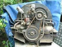 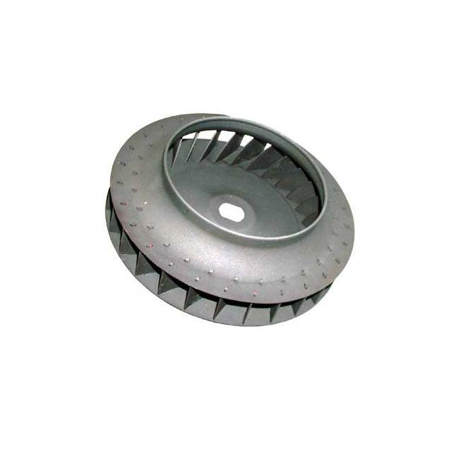 Cheers, Tony. |
||||
| rogerdw Guru Joined: 22/10/2019 Location: AustraliaPosts: 852 |
Here's a graph from a random fan I had looked at. Has a maximum unloaded flow of 1,200 CFM but a blocked pressure of 2"H2O 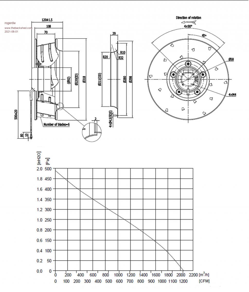  Only has a power rating of 102 watts though. 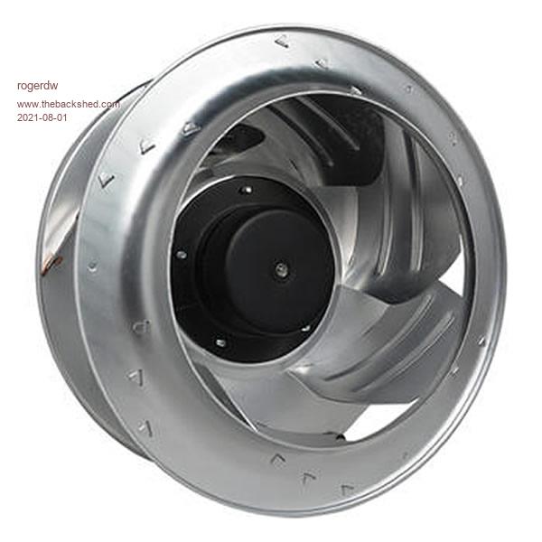 Here's the page Cheers, Roger |
||||