|

|
Forum Index : Microcontroller and PC projects : PicoMite V6.00.01 release candidates - please test thoroughly
| Author | Message | ||||
| ville56 Senior Member Joined: 08/06/2022 Location: AustriaPosts: 125 |
Thanks Peter, the binaries for both flavours of Webmite now work. Gerald 73 de OE1HGA, Gerald |
||||
| Volhout Guru Joined: 05/03/2018 Location: NetherlandsPosts: 4374 |
Hi Peter, I did not want to pollute the release thread, that is why I post here. I have questions about the PIO assembler. 1/ There is 1 PIO program memory per 4 state machines. In the PIO assembler you can use the directives .WRAP and .WRAP TARGET that can be used as addresses in the PIO(EXECCTRL) But for 4 state machines, I would need .WRAP0, .WRAP1, .WRAP2, .WRAP3 and associated targets because each state machine has it's own wrap_target and wrap addresses. Is that implemented, and if yes, then how can I use it ? 2/ In the PIO instructions there is a possibility to use side_set. The side set bits and the delay bits share 5 bits in each instruction (bits 12,11,10,9 and 8.)  When using 1 side set bit (by using PIO ASSEMBLE n,".side_set 1") bit 12 is the side set bit, and bits 11,10,9,8 can be used for delay. The assembler correctly processes this. When using side set it is brute force (each instruction uses it). While implementing a PIO UART, I need to use the SIDES_SET_ENABLE bit (only execute side set when explicitly stated in the mnemonics). This is enabled by setting the bit in the execute control register (correctly implemented in 6.00.01). But the assembler also needs to know, because the 5 bits in the side_set/delay field get another destination: bit 12=side set enable, bit 11 is the side set bit, bits 10,9,8 are delay. What is the assembler switch that enforces this change ? I tried ".side_set_en", ".side_set_enable", ".side_en", ".side_enable", but all give errors. I currently use a work around by "simulating" the side_set_enable as a second side_set bit. This is to enforce the assembler to generate the correct codes. example code: ' note: side enable is implemented as the msb side_set bit since assembler ' does not support .side_enable directitive AFAIK. ' instruction bits 12 11 10 9 8 ' official side_en side_set delay ' here sideset_m sideset_l delay ' this works because when side set not in menmonic, 0b00 is used, and enable is off PIO ASSEMBLE 1,".program uart_tx" PIO ASSEMBLE 1,".side_set 2" 'PIO ASSEMBLE 1,".side_set 1" 'PIO ASSEMBLE 1,".side_enable" ?? pio assemble 1,".line 0" PIO ASSEMBLE 1,"set pindirs, 1" PIO ASSEMBLE 1,".wrap target" PIO ASSEMBLE 1,"pull block side 3 [7]" 'PIO ASSEMBLE 1,"pull side 1 [7]" PIO ASSEMBLE 1,"set x, 7 side 2 [7]" 'PIO ASSEMBLE 1,"set x, 7 side 0 [7]" PIO ASSEMBLE 1,"bitloop:" PIO ASSEMBLE 1,"out pins, 1 " PIO ASSEMBLE 1,"jmp x-- bitloop [6]" PIO ASSEMBLE 1,".wrap" PIO ASSEMBLE 1,".end program list" Please advise, Volhout Edited 2024-12-31 06:12 by Volhout PicomiteVGA PETSCII ROBOTS |
||||
| Volhout Guru Joined: 05/03/2018 Location: NetherlandsPosts: 4374 |
Hi Peter, The correct way around the issue 1 in above post (.wrap0/.wrap1/etcc issue) is to allow multiple programs with different names to be assembled. Like this: ' SM0 code ------------------------------------ PIO ASSEMBLE 1,".program sm0" pio assemble 1,".line 0" PIO ASSEMBLE 1,".side_set 2" 'PIO ASSEMBLE 1,".side_enable" ?? PIO ASSEMBLE 1,"set pindirs, 1" PIO ASSEMBLE 1,".wrap target" PIO ASSEMBLE 1,"pull block side 3 [7]" PIO ASSEMBLE 1,"set x, 7 side 2 [7]" PIO ASSEMBLE 1,"bitloop:" PIO ASSEMBLE 1,"out pins, 1 " PIO ASSEMBLE 1,"jmp x-- bitloop [6]" PIO ASSEMBLE 1,".wrap" PIO ASSEMBLE 1,".end program list" print pio(.wrap target),pio(.wrap) 'SM1 code -------------------------------------- PIO ASSEMBLE 1,".program sm1" pio assemble 1,".line 10" '<---- preferable not needed (*) PIO ASSEMBLE 1,".side_set 1" PIO ASSEMBLE 1,"set pindirs, 1" PIO ASSEMBLE 1,".wrap target" PIO ASSEMBLE 1,"pull block side 1 [7]" PIO ASSEMBLE 1,"set x, 7 side 0 [7]" PIO ASSEMBLE 1,"bitloop2:" PIO ASSEMBLE 1,"out pins, 1 " PIO ASSEMBLE 1,"jmp x-- bitloop2 [6]" PIO ASSEMBLE 1,".wrap" PIO ASSEMBLE 1,".end program list" print pio(.wrap target),pio(.wrap) But the assembler does not allow this. It gives an error at the last line (label not found). Volhout (*) the addres counter is needed inside a program , where as it could be a global (placed before the first ".program" and inheritted at the second program. But current assembler needs it inside the program. PicomiteVGA PETSCII ROBOTS |
||||
| matherp Guru Joined: 11/12/2012 Location: United KingdomPosts: 9321 |
.side_set n opt As per the sdk Directive must appear before instructions NB: the MMBasic assembler only allows a single program to be specified this is a limitation of the implementation. The full specifications says Edited 2024-12-31 18:44 by matherp |
||||
| Volhout Guru Joined: 05/03/2018 Location: NetherlandsPosts: 4374 |
Thanks, Any description of the side_set options? I do not have the sdk installed. Volhout PicomiteVGA PETSCII ROBOTS |
||||
| matherp Guru Joined: 11/12/2012 Location: United KingdomPosts: 9321 |
Its in the sdk manual .side_set <count> (opt) (pindirs) If this directive is present, <count> indicates the number of side-set bits to be used. Additionally opt may be specified to indicate that a side <value> is optional for instructions (note this requires stealing an extra bit — in addition to the <count> bits — from those available for the instruction delay). Finally, pindirs may be specified to indicate that the side set values should be applied to the PINDIRs and not the PINs. This directive is only valid within a program before the first instruction |
||||
| Volhout Guru Joined: 05/03/2018 Location: NetherlandsPosts: 4374 |
Hi Peter, The ".side_set 1 opt" worked. Thanks. But I am still trying to find out how one state machine can use side set pins, and the other state machine not, or different. Also the text you listed from the SDK says a program is valid until a new ".program xxx" or an ".end program" Well, a new program ".program xx" can not be assigned. Therefore it seems all defines (as ".side_set x" and ".line x") are global defines, for all state machines. That feels wrong. Volhout PicomiteVGA PETSCII ROBOTS |
||||
| matherp Guru Joined: 11/12/2012 Location: United KingdomPosts: 9321 |
You will have to assemble as two programs and then concatenate the hex Edited 2024-12-31 20:22 by matherp |
||||
| Volhout Guru Joined: 05/03/2018 Location: NetherlandsPosts: 4374 |
Hi Peter, Inconvenient, but with copy and paste from the terminal screen it is possible to get the ".end program list" text into an array. Done that before. Thanks for the explanations Volhout PicomiteVGA PETSCII ROBOTS |
||||
| twofingers Guru Joined: 02/06/2014 Location: GermanyPosts: 1333 |
HI Peter, I'm wondering if it's still desirable to report errors and inconsistencies compared to the manual. If so, in this thread? I can well imagine that you're very exhausted after the last release and don't want to see anything for now. Kind regards (and a happy new year) Michael causality ≠ correlation ≠ coincidence |
||||
| Mixtel90 Guru Joined: 05/10/2019 Location: United KingdomPosts: 6946 |
There are no more errors or inconsistencies. ;-) Mick Zilog Inside! nascom.info for Nascom & Gemini Preliminary MMBasic docs & my PCB designs |
||||
| matherp Guru Joined: 11/12/2012 Location: United KingdomPosts: 9321 |
Any inconsistencies with the manual please post on the manual thread |
||||
| andreas Senior Member Joined: 07/12/2020 Location: GermanyPosts: 225 |
I have the same problems. did a flash_nuke.uf2, installed the WebMiteRP2350V6.00.01.uf2 firmware and there was no wifi connection possible. WebMite MMBasic RP2350A Edition V6.00.01RC1 was the latest working in my setup. I see that there is an update from peter, will try that. -andreas |
||||
| JohnS Guru Joined: 18/11/2011 Location: United KingdomPosts: 3831 |
This SDK PDF might be enough. John |
||||
| matherp Guru Joined: 11/12/2012 Location: United KingdomPosts: 9321 |
Harm Have you tried just having two blocks of assemble program, end program in your code? As far as I can see the code only sets instructions in the relevant bit of the PIO memory. Please test and let me know |
||||
| WhiteWizzard Guru Joined: 05/04/2013 Location: United KingdomPosts: 2839 |
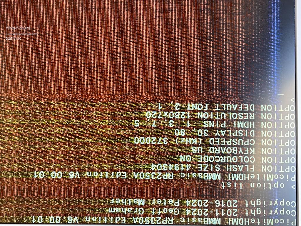
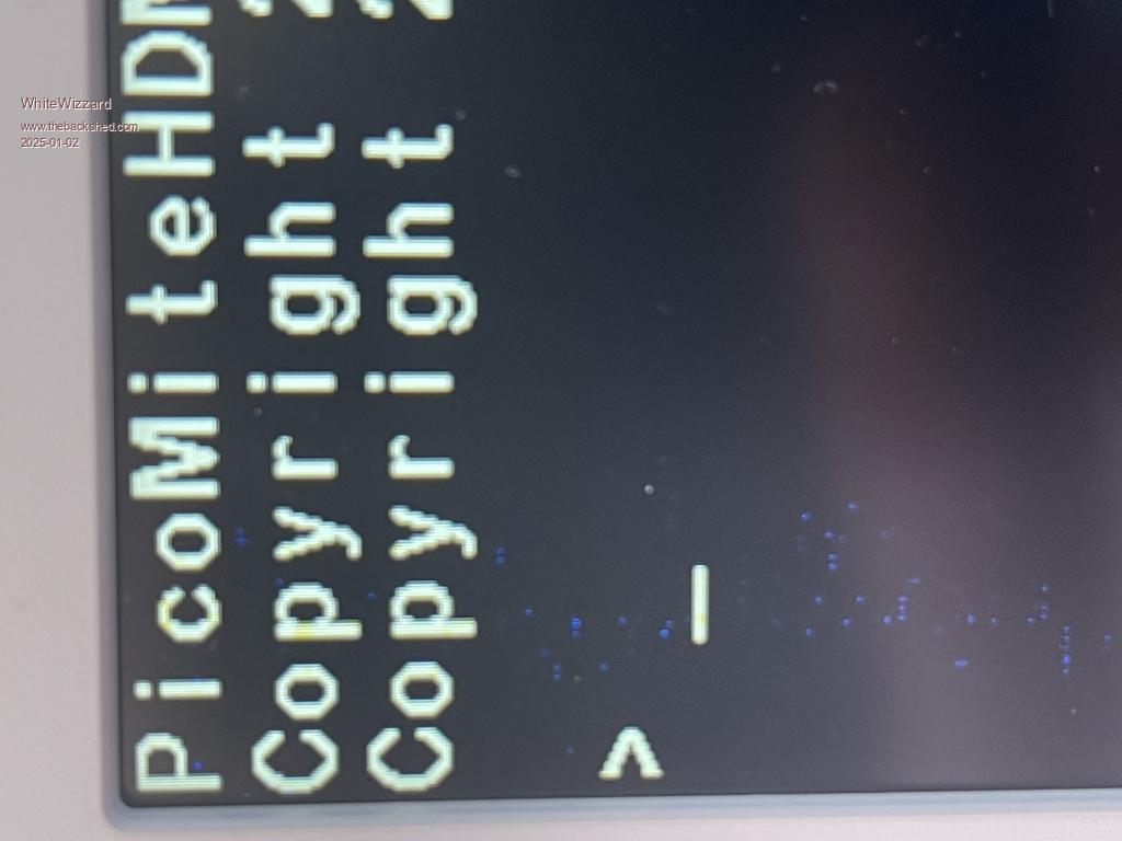
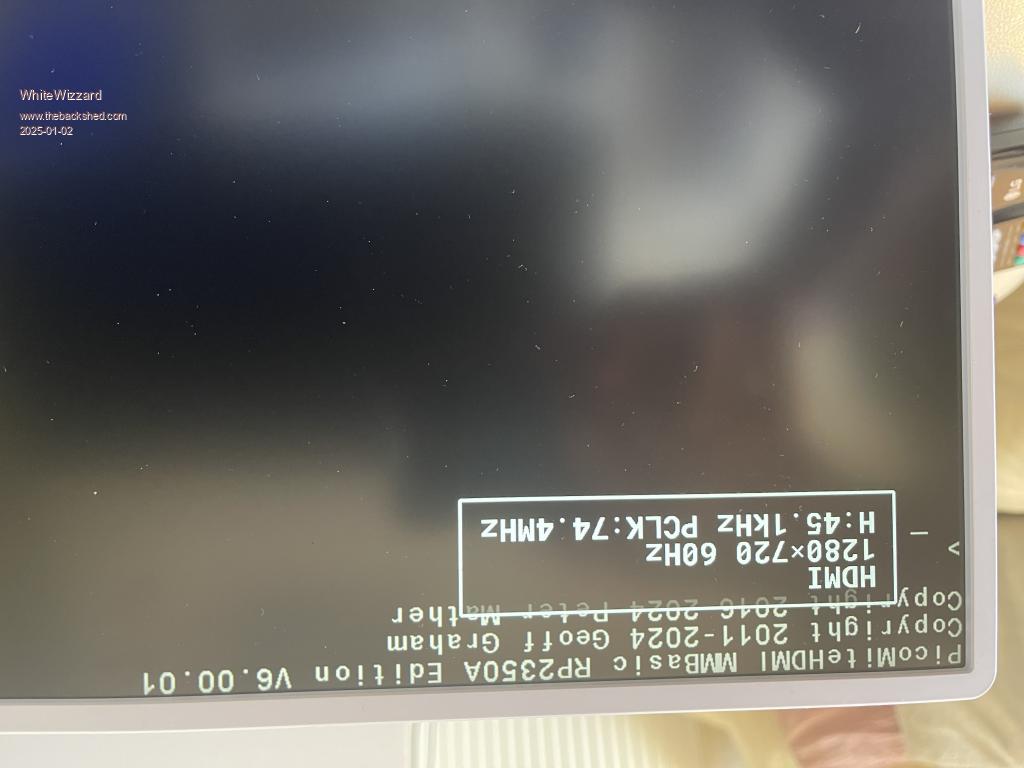
Hi Peter, Using a genuine RPi Pico 2 on an Olimex carrier (for HDMI output - and for SD card when ready to configure). I am seeing ‘noise’ on the screen and am wondering if it has anything to do with potential track length differences for the video signal-lines - your thoughts suggestions welcome….. Screenshot shows version number and OPTION settings (not sure why it is upside down!) Note that placing my finger near/on the pins will affect the amount of noise displayed - this is the extreme shown immediately below.  Here is the best I can get (but still shows a column of noise).  Tried various leads, good power sources for monitor and laptop - Pico/Olimes powered via USB from laptop for monitoring via TeraTerm.  Edited 2025-01-03 06:56 by WhiteWizzard For everything Micromite visit micromite.org Direct Email: whitewizzard@micromite.o |
||||
| Mixtel90 Guru Joined: 05/10/2019 Location: United KingdomPosts: 6946 |
Have you tried a different monitor? I have a AOC which, although HDMI and will work with everything else I've tried will not work properly using the DVI signal (which is what it is) from a Pico. A different monitor, older and with a poorer spec, works perfectly at all resolutions. From my own experimentation I don't think the track lengths are making as much differences as we first expected, at least not at 640x480. Even my Alpha board would run that resolution once I'd found the monitor issue and I'd paid no particular care to equalize trace lengths. My own suspicion is that having to include over 200R on each leg of each loop completely ruins everything to do with signal termination. It's absorbing all the junk on the loops. We have to have it because the Pico's outputs can't safely produce enough drive current for the cable and monitor. Mick Zilog Inside! nascom.info for Nascom & Gemini Preliminary MMBasic docs & my PCB designs |
||||
| matherp Guru Joined: 11/12/2012 Location: United KingdomPosts: 9321 |
No idea - works fine for me "OPTION RESET OLIMEX" will configure the board correctly Make sure the HDMI 5V out link on the bottom is connected |
||||