
|

|
Forum Index : Electronics : Inverter building using Wiseguys Power board and the Nano drive board
| Author | Message | ||||
| KeepIS Guru Joined: 13/10/2014 Location: AustraliaPosts: 1679 |
I have confirmed that our very sensitive LED battens lights in the woodworking area and my electronics section now only "blink" from bad distortion causing sudden surge loads in most cases. However, the old "diode in series with the heating element" crap for LOW setting on the Heat gun, and the Wife's Hair drier, don't cause a problem any more and are barely audible - power sharing between two toroids obviously helps. A PWM controlled Heat Gun has a sweet spot that makes the lights flicker away, but no noise from the Inverter. There are obviously a number of reasons for the improvements, and halving the power in each power stage and the amount of steel in SIX Toroids would help. The Dust-Extractor with its 500A 100Hz peak startup load does not make any difference to other equipment running, including an Aircon just above me - fan does not slow, AC compressor runs normally, and does not cause a single blink in the overhead lights. The Toroidal Power supplies that would normally cause the UPS to momentarily switch and beep, no longer do that, or blink the overhead lights. Here is a capture of the Inverter AC from a power point in the shed, trigger is at the point of switching on a 2.4kW Jug, the Inverter ticking over at 600 Watts as the Jug is powered on. Yellow: Inverter AC Output from a power point in the Workshop: Other Color: Hall current Sensor output from One Power Stage Both stages are equal and each stage is drawing around 60A DC peaks for a total Peak DC current waveform of 120A @ 100Hz. AC load jumps to 3kW - Not a single blink, even continually flicking the Jug on and off. 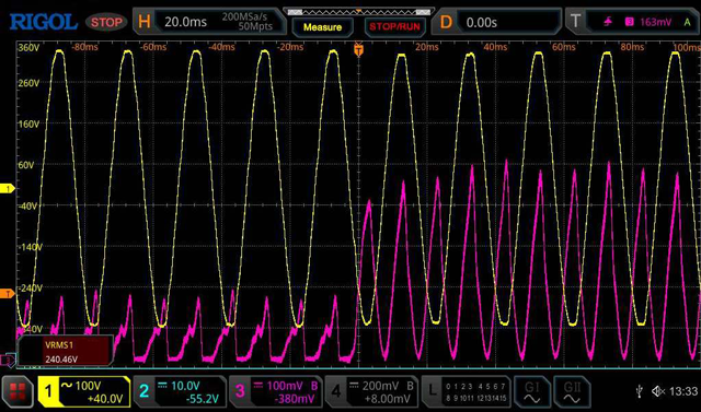 Below: Bandsaw 428A Peak DC current waveform @ 100Hz. Unlike the higher current Dust Ext, this sometimes gives the slightest flick in the lights. Things like the belt driving the lower steel wheel chirps as it slips slightly, can affect the load on the induction motor during startup. This is the worst case startup waveform I've managed to capture for the Bandsaw, depends on where in the cycle it starts. On the 1st cycle, AC dropped from 235v 218v, back to 230v by the 3nd cycle, and over 230v after the 4th cycle. 30,000uF high current screw Caps in each power Board hide and modify some of the initial current surge, the Hall Sensor does not see the current drawn from the PB Caps, and "each" Cap can easily deliver over 1000A if shorted - they can have some dampening effect on the Hall Sensors for the first cycle or so. 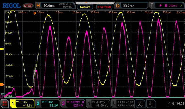 NOTE: Flat topping on the AC waveform is harmonic distortion from the other loads that are running, it's exactly the same on Mains AC. _ Edited 2024-09-15 18:15 by KeepIS It's all too hard. Mike. |
||||
| bret76 Newbie Joined: 03/02/2023 Location: FrancePosts: 18 |
What is the voltage variation at the input of the inverter (output of the batteries) when such load variations are applied (something like 4v for batteries and wiring ? for 428A ! Whoaoo). I find that the controller responds really well and fast. |
||||
| wiseguy Guru Joined: 21/06/2018 Location: AustraliaPosts: 1156 |
Phil, whilst I agree with almost everything you said I am having a problem with the gist of the last few sentences re residual magnetism. In the interests of education (me included) I looked up graphs of BH curves & residual magnetism. I believe the focus was initially related to the heating or lack of it in KeepIS's Toroids First a BH curve that shows soft iron and non silicon steel typical magnetic behaviour. 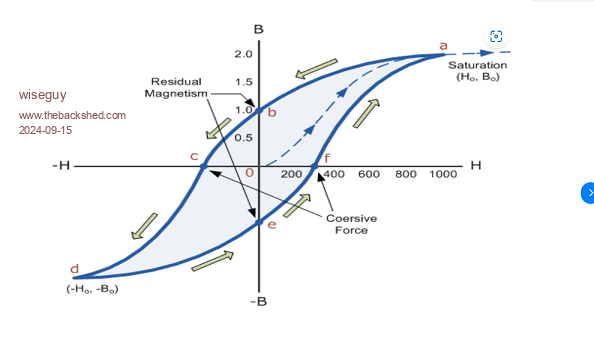 The curve shows as you stated the residual magnetism when the magnetising force is reduced to zero at the point where the graph crosses the B axis & shows maybe 50% residual magnetism. The excitation was ~ 2 Tesla, the remanence is around half that value. Now a graph showing a typical silicon steel BH curve. 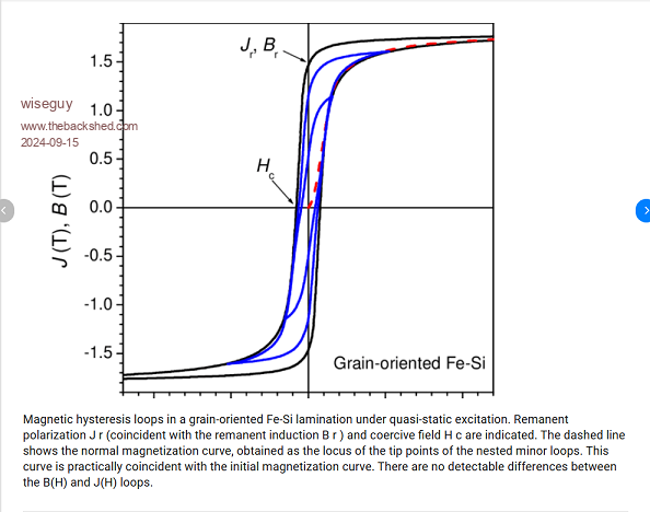 This graph shows saturation at around 1.8 Tesla but the remanence where the B axis is crossed is much higher at around 1.5. I agree, the area within the BH loop is related to losses and heating and compared to the first graph the BH area is much reduced. But there are a couple of other things to mention further, one is that we usually aim for ~ 1 Tesla in our transformers so we are well away from saturation and the BH area is thus reduced accordingly. The second is that from the graphs it appears that we can change the flux in the cores with realtively small energy input due to its permeability. The second silicon core hysteresis diagram shows higher retentivity of the material and it is closer to the saturation point. Little extra additional flux (in the same direction) would put the core into full saturation which from the graph shape is a very hard saturation. In my experience, big Toroids can make a hell of a thump and trip circuit breakers which I think also goes against "little residual magnetism"? This response is not to argue, as I am open to being corrected if I have misinterpreted the graphs etc, I don't care as much about being right or wrong, just keen to better understand the black art of magnetics. "A great deal of work went into minimizing residual magnetism in GOSS as having to reverse the residual every half cycle causes a power loss". Could it be more correct to say that a lot of work went into making GOSS material where the intrinsic magnetic domains were more readily/easily influenced (demagnetised/remagnetised) to counteract the otherwise high residual magnetism each cycle thus reducing power loss? A comment about the 1.5V cell, which could theoretically supply a current of ~ 15A with a 0.1R impedance & with 200Turns, that is equivalent to 3,000 Ampere turns which sounds significant from the 1.5V cell ? The cell should be able to cause saturation I think in either direction ? Your further comments would be appreciated. Edited 2024-09-15 23:38 by wiseguy If at first you dont succeed, I suggest you avoid sky diving.... Cheers Mike |
||||
| phil99 Guru Joined: 11/02/2018 Location: AustraliaPosts: 2134 |
Working backwards, the 1.5V cell use may well have an internal resistance greater than 0.1Ω. A repeat of the test with an ammeter in series with a similar size/type cell would be needed. Putting a multimeter straight across a new alkaline AA cell gave 5.9A. "Could it be more correct to say that a lot of work went into making GOSS material where the intrinsic magnetic domains were more readily/easily influenced (demagnetised/remagnetised) to counteract the otherwise high residual magnetism each cycle thus reducing power loss?" Yes that is a better description The graphs would have been clearer if the loops were in different colours. The smallest loop they show is for 1.1T so is closest to what you use and shows a residual of about about 1/3 of the maximum, and requires little energy to reverse. "In my experience, big Toroids can make a hell of a thump and trip circuit breakers which I think also goes against "little residual magnetism"?" They can indeed make a big thump and trip circuit breakers and the residual is a contributor but the main cause is the duration of the initial half cycle. An ideal inductor draws no current at switch-on, no matter what the voltage, then rises at a rate determined by the voltage, for as long as the voltage is applied. For an ideal inductor and a sine wave (starting at 0V) by the end of the first half cycle it will have risen to double the normal peak value. For an iron cored inductor that is the main thing that pushes the core into saturation and massive current spike. For a cosine wave (starting at Vmax) the available rise time is 1/4 cycle so the current can only rise to its normal peak value. No saturation. |
||||
| KeepIS Guru Joined: 13/10/2014 Location: AustraliaPosts: 1679 |
Well, there are 4 paralleled Banks of LiFePO4, very short connections to a thick Copper BUS. From the BUS Bar, two short 0G cables to another Two Copper Bus bar connections, in and out of a Kilovac and then straight to the Power boards on either side of the Kilovac and NEG Bus. The voltage across the Power board terminals drops from 53.9V (solar charging) to 50.1V under that 100Hz DC current waveform, so solar and float charge is always going to disappear under that load. I went to great lengths when assembling these Four 16 cell Banks of LiFePO4 to keep the DC paths as short and as heavy as possible (within reason). The result is that the voltage drop is due mainly to normal Battery voltage drop under load, and that could only be reduced by adding more parallel banks. The Toriods and controller can regulate at 240Vac output down to 44Vdc input, so how fast can the controller respond, like you said, it seem to be doing a dam good job. FYI: My low voltage cutoff is set at a nominal 52.4v However the Controller looks at the system load amperes and will hold off low voltage cutoff for some time if the load is high, but will cutoff faster under very low load with input voltage below the Cutoff. There is also an adjustable restart timer that only initializes once the set charging restart voltage is reached - this gives the batteries some time (adjustable) to at least attain a charge and tries stop power cycling from false no-load float rise in battery terminal voltage. _ Edited 2024-09-16 09:10 by KeepIS It's all too hard. Mike. |
||||
| wiseguy Guru Joined: 21/06/2018 Location: AustraliaPosts: 1156 |
Thanks for your response. A great demonstration of how words can deceive and portray a different meaning to that intended, sorry for misleading you, the 0.1R I was referring to was the measured impedance of the Toroid winding, The theoretical 15A was referring to the (previously unknown) impedance of the cell used with the 0.1R toroid. If you had used a 0R1 and voltmeter instead of a short we could also determine the AA's internal impedance  BTW I have seen a new alkaline AA battery explode its guts when shorted, it was in a card shuffler and the mechanism jammed internally - there were 4 batteries in series two of them had a spectacular death. KeepIS sorry for a bit of off topic posting & polluting your thread..... Edited 2024-09-16 10:16 by wiseguy If at first you dont succeed, I suggest you avoid sky diving.... Cheers Mike |
||||
| KeepIS Guru Joined: 13/10/2014 Location: AustraliaPosts: 1679 |
BTW the 1.5v battery was a cheap cell that was in the battery bin to be disposed off. It was connected with a frayed old jumper lead with a missing clip, just a whisker of wire on the bare end flicked across the Toroid terminal. I wasn't trying to be technical and correct, just a gut feeling I had, and a crude attempt to verify my hunch for why I was chasing my tail, trying to get this so called "resonance" peak to stick, it was one of many of those WTF moments for me. BTW thanks to both of you for expanding and discussing this topic - sooo helpful for prodding the aging brain "cell"  EDIT: KeepIS sorry for a bit of off topic posting & polluting your thread..... Just saw your edit - see above  _ Edited 2024-09-16 10:21 by KeepIS It's all too hard. Mike. |
||||
| phil99 Guru Joined: 11/02/2018 Location: AustraliaPosts: 2134 |
A little more pollution:) " just a whisker of wire on the bare end flicked across the Toroid terminal." That probably makes the circuit resistance irrelevant. With just 1.5V and the the high inductance the current will rise slowly so during a "brief flick" even for a new cell it won't rise to the resistance limited value. If it got to say 1A that would be 200At. You can see the effect using a analogue multi-meter to measure the resistance of a transformer. The needle rises much slower than normal. |
||||
| KeepIS Guru Joined: 13/10/2014 Location: AustraliaPosts: 1679 |
Final "exact" Power consumption for this 12kW Dual Toroid & Power stage Inverter. BTW I ran the previous single stage Version (same Power stage and Toroid) at 8kW for some time - heat was starting to build and could eventually be a limiting factor - but it was still NOT running hot. IMHO With plenty of cooling, this New Inverter would run at 16kW or more if needed, but I doubt I have the Solar or Battery capacity to feed it that much power for very long. I have tested this new Inverter at 8kW, but that is nothing for it, and it's all the Load I have to dump on it at the moment. I will soon have another 3.6kW load for a 12kW test run, which I already know will be easy for it. Final Readings. Idle: 49.29 Watts for the Complete Inverter in standard form. IE without assisted convection flow fans running. Idle: 62 Watts with assisted air flow (normal silent running state). As an exercise, it was interesting looking up Idle power for high cost & high end commercial 12kW Low frequency Inverters (Transformer based) Idle Consumption: usually around 230 to 280 Watts, one 12kW indicated over 300 Watts, and many do not quote the figure. I guess if these are sold online, and are to be shipped, then some transformer weight tradeoff might be in play? _ Edited 2024-09-17 18:26 by KeepIS It's all too hard. Mike. |
||||
| KeepIS Guru Joined: 13/10/2014 Location: AustraliaPosts: 1679 |
I have made a change to the Controller Code for Test Mode. It makes it a little more forgiving under some "Brain Fade" conditions, like someone could forget they left the Inverter in test mode. Makes it easier on the CAPS and Kilovac under some situations. I've also included the "Dual Code" version I'm running in the 12kW Inverter. NOTE: Both versions will work in Dual mode. See the "Latest Changes" file in the ZIP for info and how each version has changed the operation and setup features in the Inverter over time. Download Controller Hex and Info If you have any questions, please feel free to post here, as I've finally completed the Dual Inverter build. I made a second V7 backup Nano Controller, amazingly it also worked first go, and is now installed in the Inverter and running perfectly. I finally have a set of Power boards made, and 3 spare Controllers, one V6 and two V7. I will build another power board and use it and the V6 controller for testing various Toroids, I also plan to make wiseguys design for a Nano electronic Variac. There are not enough hours in the Day, although lately I feel like I'm running out of day as well  It's all too hard. Mike. |
||||
| KeepIS Guru Joined: 13/10/2014 Location: AustraliaPosts: 1679 |
Just as a matter of interest, I found a big plus (for Me) with having the four current sensor adjustments mounted separately from the Nano Controller board, which doesn't really require any modifications. When I built the second V7 controller, I simply left RV2, R15 and D6 off the board, on the previous built V7 board, I just snipped one end of D6 and linked D5. The only OC Trip input now is via the external Trip pin. The over current adjustment components "RV2, R15 and D6" AND a burden resistor of 220R replaces "R13, R14" are duplicated a few times, four in my case, on a separate board. Two for each AC over current sense transformer. Two for each DC input current sensor (without a 220R Burden resistors). The four outputs from these are paralleled through each duplicated D6 diode. A single earth and a single control voltage is connected to the Ext Trip input on the Controller. It means that the only adjustment required when swapping a Controller board, is AC output voltage via RV1 on the controller. If AC output is set when you first test the spare controller board, then no matter what levels you have set the over current trip sensors at, no physical adjustments at all are needed, just swap the Nano controller and your done. EDIT I forgot that I had shorted D5 on the old board and replaced it with a link when building the new V7 Controller. I should not post when I'm tired. _ Edited 2024-09-21 07:01 by KeepIS It's all too hard. Mike. |
||||
| bret76 Newbie Joined: 03/02/2023 Location: FrancePosts: 18 |
Let's say blue rectangle is before PWM modification (PWM at idle) and orange during big load (PWM increased). Dit the arduino send the new PWM signal at the top of the sinuzoide where the blue and orange touch ? 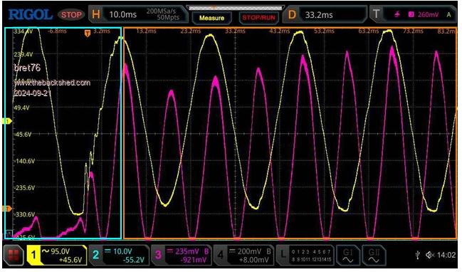 |
||||
| KeepIS Guru Joined: 13/10/2014 Location: AustraliaPosts: 1679 |
No, that's hardly half cycle from the trigger point: TP = "slight increase in DC current to the power stages". It's more an indication of the quality of the capacitor banks on each power stage, plus the stiffness of those twin "three stack" Toroidal transformers, and the efforts to minimize "unwanted" loss at every point from the Power stage outputs through to the AC output from the Toriods. However there is some design loss due the the purposeful use of a smaller gauge wire for the 4 chokes. After that you are seeing the very low loss between the Battery banks and the DC feed to each power stage as that initial current discharge from the caps is picked up fully by the DC supply. I would think by the 2nd or 3rd cycle, the Controller could have started to regulate the AC output. I would have to go back and look at the amount of filtering and design attack time for the VFB signal to the Nano. I simply don't remember. This is why there is not the slightest indication that we are running on the Inverter when an even bigger DC input surge of almost 600A starts up, it does not blink the lights. That same load causes the lights to blink when powered from the 240V AC Mains supply!! Why? Because the Main power feed is 30m away, and the Inverter-AC is in the same Shed as the workshop machinery loads. I know I'm repeating myself, but dam this Inverter has got some grunt. _ Edited 2024-09-21 19:07 by KeepIS It's all too hard. Mike. |
||||
| wiseguy Guru Joined: 21/06/2018 Location: AustraliaPosts: 1156 |
How I interpret that waveform display is as follows. The violet DC current waveform just after the idling first 2 left hand side small peaks is where the load was introduced. The DC input current reached a maximum at the point where the blue and orange touch. The voltage of the yellow waveform (AC volts out) has started to sag and continues to sag further for the rest of the next half cycle. The input current dip after the first maximum peak I assume is because the capacitor bank was initially supplying most of the current. However the next few input current peaks are increasing along with the output voltage so it appears that the feedback voltage is starting to correct now by increasing the PWM over these cycles. About 6 current cycle increases after the first minimum it appears the voltage and current have now settled and the sudden load has been corrected for. This indicates that from the point where the blue and orange coincide within about 3 complete cycles the load has been corrected for. EDIT: Whoops I started the reply before tea and finished it afterwards in the meantime KeepIS has responded to your question similarly. Edited 2024-09-21 19:39 by wiseguy If at first you dont succeed, I suggest you avoid sky diving.... Cheers Mike |
||||
| bret76 Newbie Joined: 03/02/2023 Location: FrancePosts: 18 |
I'm just interested in the small ripples in the blue square.  These appear just when the big load is switched on. I understood that the Arduino code calculates an error (following the trigger point? I don't have the code, just the picoverter code), then corrects the PWM of the sinusoid every 100Hz. So depending on the trigger point position, the PWM update may be delayed. If I rephrase my question in more adequate terms: did these ripples disappear when the Arduino adjusted its PWM or is it a coincidence? Sorry if I'm not clear enough or if I misunderstood / misinterpreted. I'm trying to understand the overall operation, but between my mind and the Austrian translation, bits are lost!!  |
||||
| wiseguy Guru Joined: 21/06/2018 Location: AustraliaPosts: 1156 |
The chokes have a resonance formed from their inductance and the output capacitor reflected back through the Toroid. Looking at the first cycle of resonance immediately after the turn on event I will guess that is around 0.5 to 1 millisecond for a complete cycle. This translates to a resonance of somewhere between 1 & 2 KHz. I did see this effect very early on in my inverter investigations. It is not a fault and it is not the Arduino doing any corrections just an artefact of the inverter output stage configuration. I believe the capacitance reflected back is 4.7uF, but it is increased by the square of the 1:8 turns ratio or 64 times. the inductor is ~ 40uH when loaded heavily, this all calculates to around 1.45kHz resonance when using 1/ (2 x pi x square root of LC), I believe this is what we see on those ripples. I think the resonance became apparent due to the sudden step change that occurred as the load was energised and the resonance started but as a decaying "ring" that settled after 6 or 7 cycles of a decayed ring. I hope this makes some sense even with the translation issues. Edited 2024-09-21 22:44 by wiseguy If at first you dont succeed, I suggest you avoid sky diving.... Cheers Mike |
||||
| bret76 Newbie Joined: 03/02/2023 Location: FrancePosts: 18 |
I have the same feeling, although I express it in a way as I can : - I am talking just about the first 50µS of the sinusoid for simplicity. At the beginning, the capacitor is discharged, the inductor discharged. I assume that there is no PWM regulation at the moment. - during "Ton" of the MOFSET, the inductor charges (current in the inductor increases). The inductor always charges with the same energy (because it charges for XXµs). - during "Toff" of the MOFSET, the inductor transmits its energy (current of the inductor decreases) to the capacitor which charges, but also to the load. - the capacitor during the charging stabilizes the voltage and the discharge current of the inductor. - at the end of the 50µs period, the voltage must have "risen" to follow the theoretical sinusoid. Something like sin(n x 2 x PI / 400) x Ubatt - If the load is low, the inductor will discharge only into the capacitor. The PWM is set for this value, everything is ok. But if the load becomes larger, this energy will have to be distributed between the capacitor and the load. The capacitor will therefore receive less energy. So the capacitor voltage will vary according to the importance of the load (so at each step, we will deviate from the theoretical sinuzoid). I have the impression that this is what we see here. Then the controller increases the "Ton" and therefore increases the energy that the inductor will store and everything will be good. - putting a larger capacitor would improve stability, but would imply a smaller inductance which would require more current to charge, therefore more losses. So it seems that there is a trade-off to be made between losses and stability (in electronician words: to choose the resonance frequency  ). ).This is what I'm trying to understand little by little....don't hesitate to tell me if I didn't understand anything. According to the calculations I'm trying to do (L, U, R in parallel), KeepIS seems to have found a very good compromise on its inductance value! And unless I correct the sinusoid every 50µs, I don't see how to do better!   I'm adding a diagram for clarity. I feel like I'm not playing in the same league as KeepIS, which will soon be speaking in megawatt ! 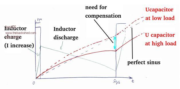 |
||||
| analog8484 Senior Member Joined: 11/11/2021 Location: United StatesPosts: 108 |
Generally more capacitance can help to a degree with tradeoffs as you mentioned. The case here is just one of many possible examples of distortions due to load disturbances. A large phase-cut load can cause even worse disturbances. Given the slow control loop update rate relative to disturbances, the most straight forward (but costly) solution to general load disturbances is to oversize the entire power system not just the capacitance relative to loads. That's basically what the grid is. Otherwise, an inverter or active power filter with much faster point-on-wave control loop scheme would be required to compensate for general load disturbances. |
||||
| wiseguy Guru Joined: 21/06/2018 Location: AustraliaPosts: 1156 |
My understanding of the Nano loop is that to compensate for a slight rise or fall in the AC output voltage (assume 240VAC) a calculation involving the magnitude of the difference between the output voltage and the reference voltage is carried out and all the FET Ton/Toff cycles for the next 360 degrees (one cycle) of mains is calculated and then applied to the next 50Hz cycle. It does not help very much to look at a single 20kHz switching period with regard to the Ton/Toff and energy in the inductor and capacitor as it will only do your head in. The capacitor voltage is affected by both the inductor charge and discharge periods, further every single Ton and Toff is different to the preceding and following cycles as the output voltage is also constantly a sinusoid on the move, so every single Ton/Toff calculation/effect is going to be different. The inductor current will only be zero somewhere near the zero crossing near 0/180/360 etc degrees, for the rest of the cycle there is an integration of the average energy in the sine wave passing through the inductor - ie a sinusoidal average DC current with a 20kHz imposed PWM energy riding on top. The current of the inductor is essentially a 20kHz sawtooth riding on top of the sinusoidal DC offset. The concept of sinusoidal DC current all in the same sentence is a bit abstract and another way of saying that the inductor current does not start and return to zero each 20kHz cycle but has a constantly changing slightly different starting and finishing point that for the switching cycle in question approximates a DC level (which is slowly changing at the fundamental 50Hz/60Hz rate). The effect of dumping a very heavy load on the output has no 20kHz Ton/Toff effect as these were predetermined before the start of the current cycle, the effect on the inverter though will be a step change of current through the Toroid and Inductor and as the previously determined on off periods are in effect they will be insufficient to maintain the current required by the load so the output voltage will droop. The sudden load step change is what causes the resonance effect between the inductor and output capacitor. If anyone can help to describe this better or relate it better to the enquiry from Bret76 please be my guest and chime in. Edited 2024-09-22 09:14 by wiseguy If at first you dont succeed, I suggest you avoid sky diving.... Cheers Mike |
||||
| KeepIS Guru Joined: 13/10/2014 Location: AustraliaPosts: 1679 |
I switched the PC off after my last post last night, I see some great information has been posted, thanks to all. This info may have been missed on my first post of this waveform. I believe that analog8484 was alluring to this, from months of real world testing, some of these disturbances are altered by other loads running on the Inverter and especially the point in the Cycle where the load is started. Out of dozens of captures of this startup cycle, this is the first time I've captured it quite like this. The Bandsaw seems to be the only induction motor load that does this, I'm wondering if the Belt slipping (drives the lower flywheel) right at power on (high frequency chirp) and very fast load variation, might be showing up in the AC waveform. I could start the same load again and the ripple would be hardly seen, normally it's a single glitch or two in the waveform, and it appears to be mainly in the Bandsaw, and it only slips when cold, and it was for that startup capture. FYI Here is an ever bigger startup from another machine at almost 600A Peak input: 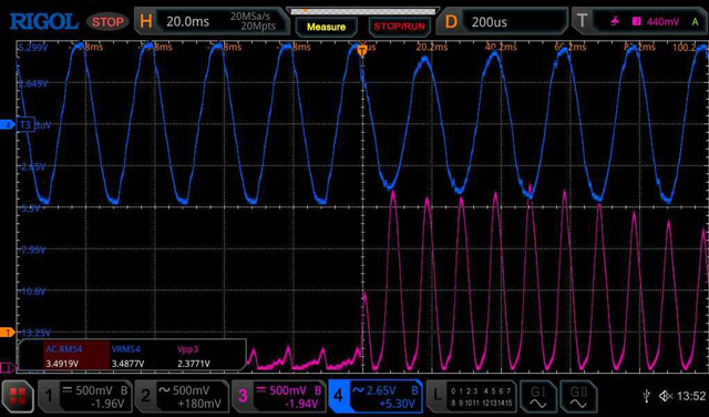 Below: The Bandsaw zoomed in at power up from a previous startup capture. 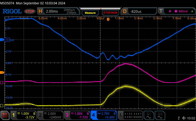 _ Edited 2024-09-22 10:41 by KeepIS It's all too hard. Mike. |
||||