
|

|
Forum Index : Microcontroller and PC projects : PicoMite: PicoGAME VGA development
| Author | Message | ||||
| Mixtel90 Guru Joined: 05/10/2019 Location: United KingdomPosts: 6822 |
I can't imagine why not, except that I don't think VBUS and VSYS are connected to the I/O connector on that version. That's easy enough to link out if you want to. I mus admit that it wasn't designed to be carved up in an optimal manner. :) Mick Zilog Inside! nascom.info for Nascom & Gemini Preliminary MMBasic docs & my PCB designs |
||||
| Tinine Guru Joined: 30/03/2016 Location: United KingdomPosts: 1646 |
Update: The flakiness that I was getting re: USB not being recognised when powering externally? Turned out to be a problem with the cheap (AE) variable power supply that I recently started using. No matter what I'm doing, if it involves switching on this PSU, it's bye-bye to USB communications. Craig |
||||
| Mixtel90 Guru Joined: 05/10/2019 Location: United KingdomPosts: 6822 |
I wonder if it might be faulty? AE have been doing supplies for a while now. Mick Zilog Inside! nascom.info for Nascom & Gemini Preliminary MMBasic docs & my PCB designs |
||||
| lizby Guru Joined: 17/05/2016 Location: United StatesPosts: 3154 |
With DVM set to buzz for a link, all 40 pins on PICO2 are connected to the corresponding pin on the 20x2 connector. Two-for-one PCB. PicoMite, Armmite F4, SensorKits, MMBasic Hardware, Games, etc. on fruitoftheshed |
||||
| Mixtel90 Guru Joined: 05/10/2019 Location: United KingdomPosts: 6822 |
Perhaps it needs some more silkscreen: "Tear along dotted line". :) Mick Zilog Inside! nascom.info for Nascom & Gemini Preliminary MMBasic docs & my PCB designs |
||||
| lizby Guru Joined: 17/05/2016 Location: United StatesPosts: 3154 |
Re that 20x2 breakout PCB cut from the "Pear" PCB, here it is: 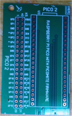 And here it is in a box: 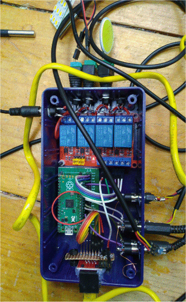 And a running example: Picomite plus 20x2 cutout PCB PicoMite, Armmite F4, SensorKits, MMBasic Hardware, Games, etc. on fruitoftheshed |
||||
| Mixtel90 Guru Joined: 05/10/2019 Location: United KingdomPosts: 6822 |
That worked out really nicely. :) Well done! Mick Zilog Inside! nascom.info for Nascom & Gemini Preliminary MMBasic docs & my PCB designs |
||||
| Mixtel90 Guru Joined: 05/10/2019 Location: United KingdomPosts: 6822 |
I've just dug out a genuine Atari joystick and I can now confirm that the Version 1.4 board works with it as expected. It was always intended to, but I just didn't have a stick handy to be absolutely certain. I've just added a link on the (next revision) board to link pins 1 and 9 on Port B. This allows GP28 to be used as the "Up" button so standard Atari switch joysticks can now be used on both ports. Normally GP28 is only used for Port B analogue paddle input. Mick Zilog Inside! nascom.info for Nascom & Gemini Preliminary MMBasic docs & my PCB designs |
||||
| pwillard Senior Member Joined: 07/06/2022 Location: United StatesPosts: 292 |
So, I have a question about power. Can you skip the DC jack and regulator if you will always power the board from the USB. Meaning... pull the 5V and 3V off of the PICO and leave the other power option parts unpopulated? It makes sense to me that you could. |
||||
| Mixtel90 Guru Joined: 05/10/2019 Location: United KingdomPosts: 6822 |
You can, but you may not be able to power some PS/2 keyboards properly if you do, it depends on the current capability of your computer's USB supply. You'll have to fiddle the board to make it work as you'll need to feed the keyboard from VSYS or VBUS. You can leave the regulator off (instructions in the construction notes) and use the onboard SMPS but it's very noisy electrically and will not be comfortable if you are using headphones. It's designed to be a little games console using a VGA monitor or VGA-HDMI converter. It's not really intended to be linked to a console permanently. You would also be relying on the micro-USB connector for power rather than the barrel jack, which is designed to be a power connector. I suspect long term reliability for the jack will be much better. Edited 2022-06-09 04:47 by Mixtel90 Mick Zilog Inside! nascom.info for Nascom & Gemini Preliminary MMBasic docs & my PCB designs |
||||
| Volhout Guru Joined: 05/03/2018 Location: NetherlandsPosts: 4262 |
Mick, Tom, You 2 are the driving force behind the picomite VGA game pcb. I have received my 1.4 board from Tom, and am starting to build it up. I think we can simplify the VGA output circuit for RED and BLUE we can use only a 270ohm resistor (no diode). for Green we can use 390 ohm and 820 ohm resitors. (no potmeter, no diode). On my monitor that is adequate. On the 1.4 board it is simply placing only these 4 parts and a jumper for R14. I noticed on the 1.4 board there is a option to disable the onboard switchmode power supply, but that coffee bean goes nowhere. The coffee bean in the 5V (default open) I have closed to get the PS2 working. Currently running of micro USB on the pico. I reworked the board to get audio corrected. I am building up the board in phases, testing each circuit as I go. 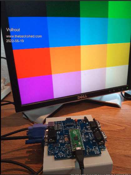 Volhout Edited 2022-06-19 19:32 by Volhout PicomiteVGA PETSCII ROBOTS |
||||
| Mixtel90 Guru Joined: 05/10/2019 Location: United KingdomPosts: 6822 |
I'd considered simplifying the video - in fact I have done on some other designs. As you say, it would be easy enough to do on this. The results look pretty good. I've not tried comparing the two yet. I'm also not sure how well the simplified design would work on all monitors, or whether the few that are using it have just been lucky. Leaving bits off saves board space, but that's all really. It hardly saves any money. I know about the SMPS inhibit - that's one of the things fixed on the next version. I could kick myself for not spotting that! lol It's lovely to see another of them running. :) Mick Zilog Inside! nascom.info for Nascom & Gemini Preliminary MMBasic docs & my PCB designs |
||||
| thwill Guru Joined: 16/09/2019 Location: United KingdomPosts: 4047 |
Hi guys, I continue to make slow progress on my little Lazer-Cycle game, but I need to finish building my 1.4 board so I can implement controller support; I'm a little worried it's going to use more CPU time than I would like. Perhaps it is a possible application for the PIO? Meanwhile the sound on my prototype board has become very clicky. I wonder if the suspect Chinese tantalum capacitor has quietly gone pop, though I understand they release white smoke? Can a capacitor be tested in-circuit? Any other culprits I should investigate? I think a simplified PicoGAME is something to keep on the back-burner just in case we ever drum-up any real interest in the platform. Though I do think the single board Pico based (retro) computer field is going to be very congested. Best wishes, Tom Edited 2022-06-19 22:27 by thwill Game*Mite, CMM2 Welcome Tape, Creaky old text adventures |
||||
| Mixtel90 Guru Joined: 05/10/2019 Location: United KingdomPosts: 6822 |
You can reduce the delay in reading the NES controllers by a long way. You don't need anything like, what was it, 12ms? I've not tried it, but you might even be able to read them during frame flyback. There may not be smoke when there's only 3.3V with limited current. You can't usually test capacitors in situ. Certainly not if they are in parallel with others. If you have a spare simply cut the suspect one out. It will probably work without anyway. :) Of course, PicoGAME doesn't have to be fully built to use it. It will run just fine with the video, Port A and a SDcard fitted to the board. You can power it using the USB socket on the Pico at a push. Everything else can be regarded as an optional extra. Build as much of it as you want/need. :) The only reason I can think of to have a simplified version is to use less PCB - but you won't necessarily save money in doing so. Mick Zilog Inside! nascom.info for Nascom & Gemini Preliminary MMBasic docs & my PCB designs |
||||
| Tinine Guru Joined: 30/03/2016 Location: United KingdomPosts: 1646 |
Eh what? What's this talk about coffee beans and SMPS??? @Volhout: I wonder if you could show a pic of what text looks like in that multi-coloured mode, please? Is that 330 X 240? Simplifying the VGA? I just got done copying Mick's circuit. TBH, I don't worry about using trimmers. There are dozens around here that haven't been touched in 30 years. A null offset would be a serious issue but they are still rock-solid. Craig |
||||
| Volhout Guru Joined: 05/03/2018 Location: NetherlandsPosts: 4262 |
Tantalum capacitors become short when defective. No smoke that I know off, unless thete is a lot of power involved. Much more than picomite circuits do. Electrolitic release smoke. Acid that is, so watch out when that happens. PicomiteVGA PETSCII ROBOTS |
||||
| Mixtel90 Guru Joined: 05/10/2019 Location: United KingdomPosts: 6822 |
The beauty of the PicoGAME (for me, as a hardware person) is that it's so flexible. You can include just the options that you want. It will always fit the same case (although it would be nice to sort out some PCB front & rear panels it's not worth doing unless there's a reasonable demand for them as it's two orders, one for each. You'd probably get 3 per 100x100 board, that's 15 panels minimum for one end only - and you still have to cut case side holes anyway, for audio and SD). I don't think there's much point in a console smaller than this anyway. Too many dangly wires. I've come up with a plan for using the space saved by simplifying the VGA. By fitting 4 resistors connected to the data lines of the USB-A socket it makes it more usable for mobile phone charging. :) Mick Zilog Inside! nascom.info for Nascom & Gemini Preliminary MMBasic docs & my PCB designs |
||||
| Volhout Guru Joined: 05/03/2018 Location: NetherlandsPosts: 4262 |
320x240 Here are (large photo's) color text on black, and color text on color background. I have no idea how the photos look in the forum. On the phone they look sharp. 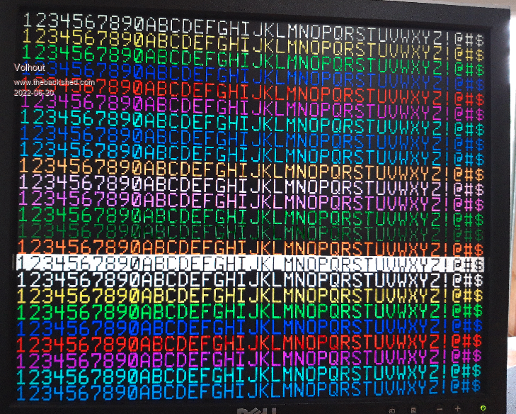 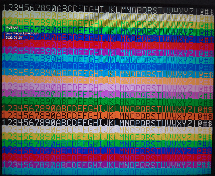 I was afraid of that, the color on color shows some artefacts that do not show on the monitor (especially on the yellow on green). Edited 2022-06-20 00:36 by Volhout PicomiteVGA PETSCII ROBOTS |
||||
| thwill Guru Joined: 16/09/2019 Location: United KingdomPosts: 4047 |
Ok, helps when I don't get milli and micro seconds confused. The NES uses a latch pulse of 12us and I've read a reference suggesting that 4us is probably all that is necessary. You also have to pulse the clock 8 times too, and you've got two controllers but given it's us not ms I'm happier now. Best wishes, Tom Game*Mite, CMM2 Welcome Tape, Creaky old text adventures |
||||
| Mixtel90 Guru Joined: 05/10/2019 Location: United KingdomPosts: 6822 |
I can't remember the times I was playing with now. I do know that on "the worst flight simulator in the world" (just a horizon line!) it became a lot more responsive if I speeded things up by shortening the time. :) The CMOS chip is pretty fast so times are probably limited by how fast MMBasic can handle it. Mick Zilog Inside! nascom.info for Nascom & Gemini Preliminary MMBasic docs & my PCB designs |
||||