|

|
Forum Index : Other Stuff : Building a Spot Welder
| Author | Message | ||||
| herbnz Senior Member Joined: 18/02/2007 Location: New ZealandPosts: 258 |
IMHO Glen As mentioned before increasing the leakage reactance would solve both problems Herb |
||||
| Dinges Senior Member Joined: 04/01/2008 Location: AlbaniaPosts: 510 |
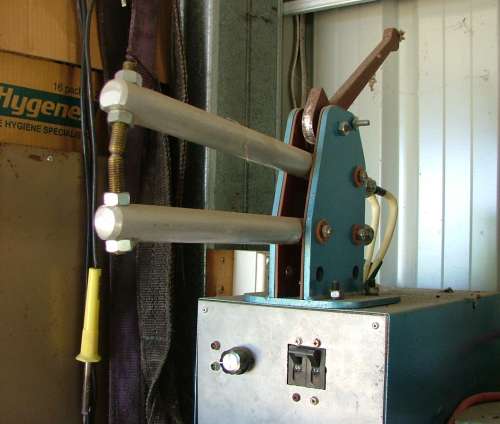
Glenn, I'm contemplating building a real spotwelder again and recalled you had built one so had to read this story again. One question though: did you finish the project and add those aluminium pinchers? Reason I'm asking is I was contemplating aluminium pinchers instead of copper. Would be a much cheaper solution. Aluminium has slightly higher resistivity than copper, but is so much cheaper that I think I could make up by simply using thicker pinchers. Doubling the diameter (as compared to copper pinchers) should more than compensate for the higher resistance, and be mechanically stiffer as well. specific resistivities: Steel = 180 ohm.meter Alu = 27 ohm.meter copper = 17 ohm.meter Copper would (for a same cross section) give 10x less resistance than your steel pinchers, but the improvement by using aluminium isn't something to be sneered at too, I think. So, curious as to what the current status of this project is, as it may save me from making (expensive) errors :) Oh - funny... I was contemplating a contactor for this project, not the solid-state relay I used before - till I read your remark.... I was worried about the 16A SSRs blowing, but IIRC I should have a few 380Vac/32A ones too lying about. Guess I'll use that one then, though I'd kind of enjoy the 'click' (*clunk*?) sound a contactor would make.... Peter. |
||||
| Gizmo Admin Group Joined: 05/06/2004 Location: AustraliaPosts: 5078 |
Hi Peter. I did add the aluminium arms. 
It was a step backwards. The steel arms had the advantage of aligning the welding tips very well. The aluminium arms have a bit of sideways movement and its hard to get a good well aligned grip at the tips. If I had used square section aluminium instead of round, I think it would have worked much better. The aluminium also, as you know, has a much lower resistance than steel. This was bad in my case, every 2nd time I used the welder it popped the main workshop circuit breaker, 20 amp rating. The steel arms had that extra bit of resistance that meant the circuit breaker would hold in when I was spot welding. I was very dissapointed with the alumnium arms, they cost money and made the welder useless, so I put it aside until I find a use the the aluminium and then I'll put the steel arms back on. I do like the idea of a capacitor discharge spot welder, got my eye out for a dirty great IGBT or SCR. Glenn The best time to plant a tree was twenty years ago, the second best time is right now. JAQ |
||||
| Dinges Senior Member Joined: 04/01/2008 Location: AlbaniaPosts: 510 |
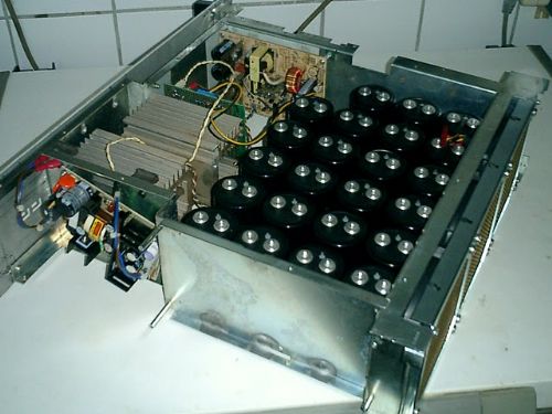
Thanks for the speedy response. [quote=Glenn]It was a step backwards. The steel arms had the advantage of aligning the welding tips very well. The aluminium arms have a bit of sideways movement and its hard to get a good well aligned grip at the tips. If I had used square section aluminium instead of round, I think it would have worked much better.[/quote] Funny, I was pondering that very issue earlier today before I posted my question. Actually contemplated using ballbearings for the pivot point (and managed to drop the drawer with bearings, spreading them everywhere - think I found most of them, but I'm expecting to find bearings in little nooks and corners for the next 10 years - but I digress), but then considered it to be overkill and am now pondering a sleeve bearing (brass sleeve bearings, 8mm ID, from old flatbed scanners; combined with a 8p7 steel pivot shaft (normally used as guides for injection moulds) this should give very little play). I think I will settle for aluminium then, based on your answer and 'problem' of breakers tripping. Have you considered removing one or two turns from the transformer, thus lowering the voltage? You may find it'll solve the problem of breaker tripping. After all, you've optimized one part of your machine (the pinchers, by reducing resistance) and now bump into another problem. I suspect your secondary voltage is too high, but it's just a guess. Easy to verify this though by temporarily removing one turn from the transformer and testing again to see if breakers trip (and the welds remain satisfactory) [quote]I was very dissapointed with the alumnium arms, they cost money and made the welder useless, so I put it aside until I find a use the the aluminium and then I'll put the steel arms back on. [/quote] I wouldn't - you've 'perfected' that part of your machine; one bottleneck was removed, now another one appears - deal with that new bottleneck (too high voltage, too small transformer, or too little grid power. Admittedly, that last one is hard to solve, but I suspect removing one or two turns from the transformer will solve the problem) [quote]I do like the idea of a capacitor discharge spot welder, got my eye out for a dirty great IGBT or SCR.[/quote] I'm still very happy with mine! I got very lucky at the time when I wanted to build my cap-discharge spotwelder. Was contemplating it for years but never found either the capacitors or the SCRs. Then by sheer luck I found both in a matter of weeks - the SCR was free, the caps were ridiculously cheap (0,80 euro per piece; 1.20 US$). Everything else was made of junked parts. The SCRs that I found were both mounted on a large cooling fin. One was broken, but the other one was still working. I strongly suspect it came out of a thyristor welding machine. If there are welding machine repair shops in your area, pay them a visit and ask to have a look in their garbage bin (maybe bring a 6-pack for the guys in the shop?). If they are replacing a complete thyristor module and throw out the old one, there's a good chance one or two of them are still working.... Hard to see in that picture, but are you using brass tips? If so, keep in mind that brass has very high resistivity, rendering it useless in this application. (though, in your case, it'd probably help to protect the breaker...  ) )
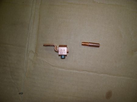
One good idea for electrode tips I found a few days ago was using MIG nozzles (on the right in this picture): 
Idea came from here: http://hackaday.com/2009/06/23/how-to-build-your-own-spot-we lder/ If you drill and thread a hole in the aluminium pinchers and install those nozzles as electrodes, you'll be able to spotweld in much tighter places. Also, replacing those nozzles will be quick and easy. Last time I bought a bunch of them, they were dirt cheap too; 1E/pce or so. I can't make electrodes cheaper myself.... Peter. (<-- wishes he had a few more of those SCRs) edit: instead of one big SCR, you could also use a bank of MOSFETs. In fact, that's what commercial manufacturers of CD spotwelders do. MOSFETs can be turned off, unlike thyristors. Also, it'd be easy to do a 'double-pulse' weld - small initial pulse to clean the weldzone, then blast it with the full main pulse. This seems to produce superior welds - at least, according to the manufacturer). I bet that car controller Oztules posted a few days ago wouldn't make a bad switch for a CD welder either.... |
||||
| Robb Senior Member Joined: 01/08/2007 Location: AustraliaPosts: 221 |
How about putting the steel arms back and running copper cables right to the end of the arms. |
||||
| Gizmo Admin Group Joined: 05/06/2004 Location: AustraliaPosts: 5078 |
You know, thats a good idea. I took a turn off the transformer like Peter suggested and it now welds without blowing the circuit breaker. Yes, those tips were brass, I figured brass wouldnt stick to the work piece, didn't even think about the resistance. I'll see if I can find some copper tips. Glenn The best time to plant a tree was twenty years ago, the second best time is right now. JAQ |
||||
| Dinges Senior Member Joined: 04/01/2008 Location: AlbaniaPosts: 510 |
Good to hear it works better now! It's nothing more than the application of P=U*I... if we want to reduce P without reducing I, we should reduce U (voltage). By adding resistance, transformer voltage U stays the same whilst current I decreases. Lowering I is not a good thing for spotwelders. As you've now got a copper cable that is 30-40 cm too long (no longer wound around the transformer core), another thing you could try next is shortening this cable, thus reducing its resistance a little more. Down side is that, if it starts tripping breakers again, you'll have to make a new transformer winding (or add a short length of steel strip with holes for the bolts, to work as a small resistance, high-power resistor). But if it works, you may succeed in upping the current capability of your machine by another 10-20%. I recall being very surprized when I learned for the first time about the large resistivity of brass. (65*10^-9 ohm.meter, around 3 times the value of aluminium, 4 times that of copper) Peter. |
||||
| PeterKesel Newbie Joined: 07/11/2009 Location: Posts: 3 |
Good idea.I drew up and lasercut parts for the spot welder "pincher" today. The parts were cut from 12mm and 5mm steel plate. HID Kit |
||||
| Ron B Newbie Joined: 26/04/2013 Location: AustraliaPosts: 5 |
I tried connecting with the URL to Dinges gallery album but it's dead now. Does anyone havwe a way of finding this link? Cheers! 
|
||||
| vasi Guru Joined: 23/03/2007 Location: RomaniaPosts: 1697 |

[quote] The gallery is temporarily down.. It's overall a complicated problem, but this is the basic explanation. The gallery is hosted on another server than the forum, as it has a significantly larger connection.. Because of extreme cold the connection to this server has failed.. We have not seen this kind of sustained cold in the area for over 6 years. Since a lot of the new tech that runs the internet connections here in northern Mn are newer than that they have never been stressed like they were recently, and some pretty strange things have happened over the last few days. Some problems took out a very large portion of our area, including phones/cells. I have been told that this connection cannot be fixed for several days, so I wil be physically visiting the gallery's server to relocate the data to the same server as the www until that connection is back online. This is nearly 30 mile trip (one way), and a large portion is on a hilly / icy small back road. Funny how they pick a middle-of-no-where back road to run a major fiber optic line huh? Lets hope the connection here holds up here :o [/quote] Now the Gallery is a subdomain: http://gallery.anotherpower.com but the site right now is down/ Oops! The last post here was in April! Sorry! 
Hobbit name: Togo Toadfoot of Frogmorton Elvish name: Mablung Miriel Beyound Arduino Lang |
||||
| Wombat Regular Member Joined: 27/05/2011 Location: AustraliaPosts: 72 |
Wow, long time since I read this thread. I enjoyed it then, and enjoyed in again. This time I'll remember how to accurately measure low resistance. 
Cheers! Russ  |
||||
| iconrl Newbie Joined: 24/09/2011 Location: United StatesPosts: 4 |
Here's a pretty good video of how someone built this. Make a spot welder |
||||