|

|
Forum Index : Solar : PL20 + SSR 12V Solar Install - High Amps.
| Author | Message | ||||
| MOBI Guru Joined: 02/12/2012 Location: AustraliaPosts: 819 |
I think I might have mentioned it on TBS before, but we have a German made fridge and 4' chest freezer (Vestfrost) which together use less power than a mini bar fridge. The units are 240v compressor types but are very efficient and quiet as a mouse. We also do the washing and vacuuming in the morning so the batteries have a chance to be fully charged by dark. It is just a matter of life style change. The bulk of our power still comes out of the batteries during high drain as the panels are only 680 watts unless I switch on the SMA "grid" connect system - an extra 1kWatt. David M. |
||||
wallablack Senior Member Joined: 10/08/2011 Location: AustraliaPosts: 164 |

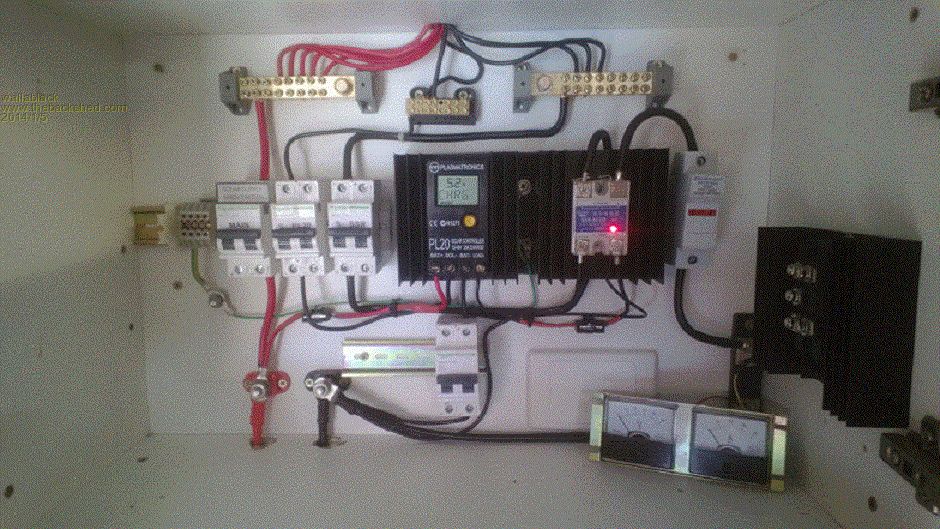
So I connected it all up today while the weather was overcast...IMO a good time to give things a bit of a pre connection test while current is low. I think there is an error, actually, I know there is an error...om the SSR side of things. PL20 Settings. PROGRAM - 4, LSET - 10, PWM - 3. Problem. Volatage reading on the PL20 was 14V and on BOOST to charge to 15V, with one panel (200W 12v)connected showing 11A. Connected another 200W 12V panel to the - bus feeding the SSR S-, ammeter reads 10A still at 14V....then I measured the voltage on the main positive bus and the SSR - bus and the voltage went to 17V...a bit high I would think. Turning the SSR feed off this reading went to 21V...unconnected open voltage, so it seems as though it is connecting. Then I connected another panel to the main positive bus and the SSR S- bus and the SSR stayed at 11A and the voltage went up to 19V. Then it stopped completely. Do I need a reverse blocking diode on the Solar Negative feeding the SSR...Plasmatronics literature says I "will need a reverse blocking diode on extra connected solar arrays"...do I put one in the negative feed in? Foolproof systems do not take into account the ingenuity of fools. |
||||
fillm Guru Joined: 10/02/2007 Location: AustraliaPosts: 730 |
Good to see a Neat wiring Job! You have the G - Set on 3 this is PWM , I would say the batteries were charged and the PL20 was Regulating the Batt V then it switched out of boost to Absorb . You could try setting G-Set to 0 or 1 as this will slow things down to see what is going on , you can also manually switch the Boost cycle back By long presses when reading Batt V.. You should have a reverse current protection diode on the SSR control. I would think Blocking diodes would be fitted to the Solar Panels. Also check current is passing through the SSR correctly , it appears you are correct, PhillM ...Oz Wind Engineering..Wind Turbine Kits 500W - 5000W ~ F&P Dual Kits ~ GOE222Blades- Voltage Control Parts ------- Tower kits |
||||
wallablack Senior Member Joined: 10/08/2011 Location: AustraliaPosts: 164 |
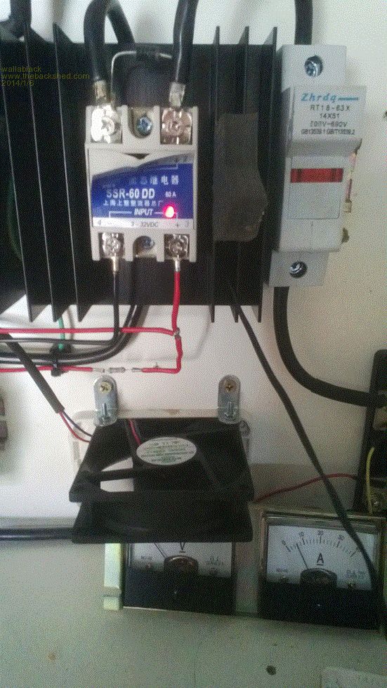
Thanks Phill, I always like to have things tidy and easy to follow. I am getting a good understanding of the PL20...love it. So SET/MODE/GSET=0 or 3... 0 is "on when a function wants to disconnect battery" and 1 is "off when a function wants to disconnect a battery"...seems to be a difference between the two, which is more recommended would you think. I cooked one PL20 "assuming" I had it right and I don't want to do that again. Also I am not trusting things enough to put my good 100A SSR on at the moment. I have a few 60A cheaper Chinese SSR's and the temp probe on the SSR's big heatsink reached 70 degrees at only 16A, slightly melting the SSR. Then I installed a 75mm fan and the temp dropped to 36 degrees almost straight away. The photo is showing only 8A at this stage well after. 
I still dont think I have things tethered out yet as I thought I would be reading more amps through the SSR.... Foolproof systems do not take into account the ingenuity of fools. |
||||
fillm Guru Joined: 10/02/2007 Location: AustraliaPosts: 730 |
Wally, The catch diode is on the wrong side of the SSR , it is shown in the PL Wind it should be accross the load terminal and B+ . It is best fitted at the PL or can be accross 3 and 4 on the SSR . Bar on Diode goes to B+ or 3. You might need to try set LSET to 11 ( YOU MUST NOT USE PWM 2 or 3 WITH 11) as I think you set up is working in Reverse , when your B voltage reaches the Volt setpoint the solar on the pl is regulating and then the SSR turns on this will increase battery Volts with the external and regulate on the PL , one is fighting the other. Check if this is the case , apply a load and drop below Bat V set point the PL will show amps in and the ext PV will turn off . Test first before any changes and fit the catch diode. I ALSO MIXED L SET TO G SET IN THE PREVIOUS, sorry I mixed them as you are not using Gset. PhillM ...Oz Wind Engineering..Wind Turbine Kits 500W - 5000W ~ F&P Dual Kits ~ GOE222Blades- Voltage Control Parts ------- Tower kits |
||||
wallablack Senior Member Joined: 10/08/2011 Location: AustraliaPosts: 164 |
I honestly thought something was not right with the catch diode. The download from Plasmatronics which was written by RPC states "a catch diode should be placed across the output of the SSR (band of diode to the battery negative side)". Now if you go to the RPC website and look at their literature now it doesn't even make mention of a catch diode. Foolproof systems do not take into account the ingenuity of fools. |
||||
wallablack Senior Member Joined: 10/08/2011 Location: AustraliaPosts: 164 |
SUCCESS!!!    
Thanks for that Phill. Twas the catch diode I reckon... and I put in my good SSR too so it was one of the other. Left the settings at LSET = 11 and PWM = 3. Odd that on the literature it said to put the catch diode across 3 & 4..I thought it seemed unusual. I don't think the idea here is to "divert" as you would with wind and to use the SSR to shift current but rather use the SSR to duplicate the actions of the PL20. So LSET is off when a function wants to disconnect the diversion load... Well...I have 1 x 120W 12V panel connected to the PL20 and 3 x 120W 12V and 2 x 200W 12V panels connected via the SSR.......had 9.7A at the PL20 and 40A at the SSR at 4pm...not bad...beat the 10 - 20A I was getting. I cant quite tell but I was at 13.9V when I did these readings so in all it would be 135.8W (from a 120W panel?..it is pretty good sun today I guess and windy) and 556W from the rest...the 2 x 200W are not in prime position though so it's understandable. Foolproof systems do not take into account the ingenuity of fools. |
||||
wallablack Senior Member Joined: 10/08/2011 Location: AustraliaPosts: 164 |
Oh Dear...now I feel like TomQ throwing in a million questions... As soon as it changes from BOOST (15V) to ABSB (14V) the SSR keeps pumping through the current and the PL20's current stops as it is meant to so it never gets to 14V to ABSB..well the PL@) thinks it is at ABSB but with the 30A+ going through the SSR it really isn't. ABSB TIME is now at 0.4 (24m) and the SSR is still going and the battery bank is at 14.7V..... Foolproof systems do not take into account the ingenuity of fools. |
||||
fillm Guru Joined: 10/02/2007 Location: AustraliaPosts: 730 |
Wally, You might need to read back on my previous , if you have selected L set 11 you CAN NOT use 2 or 3 PWM .... 1 or 0 only I don't know what RPC do , I go by Plasma web site . The Diode can go at the Pl or at the SSR , I would do the PL20. Link to Plasmatronics probably better off to have a good read this one PL Manual page 27 shows catch diode . PhillM ...Oz Wind Engineering..Wind Turbine Kits 500W - 5000W ~ F&P Dual Kits ~ GOE222Blades- Voltage Control Parts ------- Tower kits |
||||
wallablack Senior Member Joined: 10/08/2011 Location: AustraliaPosts: 164 |
Sorry it was meant to read LSET=10, PWM=3. The PDF I downloaded was on the the Plasmatronics website so I assumed it to be credible information. HERE Go to PL Series > Common PL FAQ's > 6. This is where I got the settings info from....and also the catch diode info, have a read at the bottom of the page. That is where I got the SSR document from which is on the Plamatronics website care of RPC RPC (Rainbow Power Company) This link goes to their website and also to a doc that does not even mention a catch diode. See my confusion 
So their recommended LSET=10 and PWM=3 is not right? Foolproof systems do not take into account the ingenuity of fools. |
||||
fillm Guru Joined: 10/02/2007 Location: AustraliaPosts: 730 |
WALLY, As I mentioned before and appears to be what you described , your system is working in reverse ... You need to change the settings . Phill PhillM ...Oz Wind Engineering..Wind Turbine Kits 500W - 5000W ~ F&P Dual Kits ~ GOE222Blades- Voltage Control Parts ------- Tower kits |
||||
| yahoo2 Guru Joined: 05/04/2011 Location: AustraliaPosts: 1166 |
LSET = 11 and PWM = 1 will still give you PWM on the dingo. the SSR switch speed is adjusted up by shortening the hysteresis voltage menu SET> REG> HYST 0.1-1.0 volt I'm confused, no wait... maybe I'm not... |
||||
wallablack Senior Member Joined: 10/08/2011 Location: AustraliaPosts: 164 |
Okay...With PL20 at BOOST now and BATV @ 12.2V. LSET=11 and PWM=0...no solar current going through SSR LSET=11 and PWM=1...no solar current going through SSR the SSR switch speed is adjusted up by shortening the hysteresis voltage menu SET> REG> HYST 0.1-1.0 volt I have the HYST set at 0.6V. PWM=1 on the PL20 will give you PWM on SOL- terminal only. Foolproof systems do not take into account the ingenuity of fools. |
||||
fillm Guru Joined: 10/02/2007 Location: AustraliaPosts: 730 |
Wally , Well , I do not know what is wrong with your system . I have just tested a PL20 here with a SSR on a variable power supply. In L-set 10 when the volts reach the set point the SSR turns on as required for a wind / hydro control . In L-set 11 " inverterted shunt control " the SSR is on until the V set point is reached. With PWM set to 1 you should get PWM on the SOL Input and regular switching on L terminal . This should be adequate for your set up as the solar into the SSR is for Bulk Charge. You should be set to L- Set 11 / PWM 1 and use the Hysteris to adjust your switching speed . ( You will not get PWM on the SSR in this Config ) "Make sure you are setting L-Set and not G-set" PhillM ...Oz Wind Engineering..Wind Turbine Kits 500W - 5000W ~ F&P Dual Kits ~ GOE222Blades- Voltage Control Parts ------- Tower kits |
||||
| yahoo2 Guru Joined: 05/04/2011 Location: AustraliaPosts: 1166 |
I think we are assuming that you have wired it load- through the SSR input to the B+ from looking at your photos. the rpc document shows a different circuit. sorry I didn't look at that. if you have wired the same as the rpc diagram then as I see it on LSET 10, as the voltage drops the load terminal switches off, presumably then the current flows B- to B+ triggering the SSR. is this supposed to be a balancing circuit like a charging light on a car alternator? if that is the case then the wiring from the load terminal to the resistor needs to have equal or lower resistance than the B- through the relay wiring so that it takes priority......I think I am having trouble visualizing the path and connections and if there is supposed to be some electrical isolation of some components, this whole -gative active thing does my head in sometimes. I have the same trouble wiring the old fordson tractors with an alternator I'm confused, no wait... maybe I'm not... |
||||
wallablack Senior Member Joined: 10/08/2011 Location: AustraliaPosts: 164 |
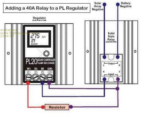
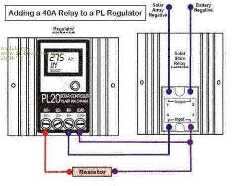
Below is a copy/paste of the download available from the Plasmatronics website... This is exactly how I have it set up (excluding the usual PL20 wiring which is not shown in this diagram)but at the bottom of the text is states to put the catch diode on the SSR 1 & 2 terminals. BELOW IS THE DOCUMENT FROM THE PLASMATRONICS WEBSITE. Phill, on your test did you have it wired different than how I have...I think this is causing the confusion. Increasing the Charging Capability of Your Plasmatronics PL Regulator 
This configuration is used to handle currents higher than your existing regulator’s maximum rating without having to replace your regulator with a larger one. It is also used to increase the capability of large systems already equipped with the PL60. Extra strings of panels (up to 40 amps per relay) are connected to the battery bank as follows: The battery negative wire is connected to terminal ‘2+’ on the relay, and terminal ‘1’ is connected to the extra solar array negative (assuming the initial solar array is being regulated directly by the PL regulator). The normal operation of the regulator is thus duplicated at the relay. The regulator program settings and the value of the resistor are as follows: (Regulator is set to REG: 4, LSET: 10, PWM: 3) (Resistor values are; 220. for 12v, 440. for 24v etc.) Note: If you wish the regulator to measure the current going through the relay, then a Plasmatronics shunt adapter and external shunt will be required. Part used in example above = Crydom D1D40 SS relay (needs large heatsink, 80W @ 40amps!). 12V systems can use a lower cost Jaycar relay = SY4086 (needs a lot smaller heatsink). Also Note: Extra connected solar arrays will need reverse blocking diodes (unless the solid state relay used is a reverse blocking design) and a ‘catch’ protection diode should be placed across the output of the Solid State Relay (band of catch diode to the Battery Negative side). Foolproof systems do not take into account the ingenuity of fools. |
||||
wallablack Senior Member Joined: 10/08/2011 Location: AustraliaPosts: 164 |

Foolproof systems do not take into account the ingenuity of fools. |
||||
wallablack Senior Member Joined: 10/08/2011 Location: AustraliaPosts: 164 |
What the above post was "meant to say" was.... I think I just broke the forum rule but copy and pasting information from an outside source....I do apologize if I have, if so feel free to remove it Gizmo. It is not copyright material though, it is open literature. Foolproof systems do not take into account the ingenuity of fools. |
||||
fillm Guru Joined: 10/02/2007 Location: AustraliaPosts: 730 |
Take the resistor out, B+ goes to T3+ on ssr , then T4 - goes to the load term ( the SSR shoud be 3~32VDC ), Lset 11 PWM 1 and it will work . I don't know why it has to be so complicated , the RPC way still uses the L term so there is no benefit to free up a terminal, So you don't get PWM on that array .... So What.... The added array is for Bulk Charge,the PL can still regulate PWM with 20A which is more than enough to do Absorb and float . If you want to go the RPC way then do what they say . PhillM ...Oz Wind Engineering..Wind Turbine Kits 500W - 5000W ~ F&P Dual Kits ~ GOE222Blades- Voltage Control Parts ------- Tower kits |
||||
wallablack Senior Member Joined: 10/08/2011 Location: AustraliaPosts: 164 |
I don't know why it has to be so complicated , the RPC way still uses the L term so there is no benefit to free up a terminal, So you don't get PWM on that array .... So What.... The added array is for Bulk Charge,the PL can still regulate PWM with 20A which is more than enough to do Absorb and float . If you want to go the RPC way then do what they say . PERFECT....BIG THANKS PHIL 
So simple....I do not understand why the other way was even documented to be honest. Foolproof systems do not take into account the ingenuity of fools. |
||||