
|

|
Forum Index : Electronics : Simple battery charger
| Author | Message | ||||
| SpmP Newbie Joined: 10/10/2010 Location: New ZealandPosts: 32 |
Hmm, I have what I think may actually work! Three pots, 1 for voltage divider off input, s.t the same circuit can be used for 12/24V with only changing the zener (or omitting it) 1 for setting Vref 1 for setting hysteresis for the relay. The hope was that the relay could cut out below the threshold for the shunt control. I have put a simple totem pole on the shunt fet in case it desires to switch really fast... (which it should do and does if you connect Bat+ to Vb instead of after the fuse. Oh and I didnt include the potentiometer.asc in the zip file! No wonder you had problems! Put it in lib/sym/ or wherever. I should improve the model so you dont need potentiometer.lib spice directive... What do you think? I think this could be quite easily setup, esp. with say a battery charger, battery and a potentiometer as a voltage divider for variable volage supple.... if you need more than vbatt + charger to set vH then derate Ri Should be set 12 input -> 4 at Vi I am sure you have far cunninger ways of doing this 8) Jasper 2012-05-04_093146_battery-relay_solar-shunt_control.zip |
||||
| larny Guru Joined: 31/10/2011 Location: AustraliaPosts: 346 |
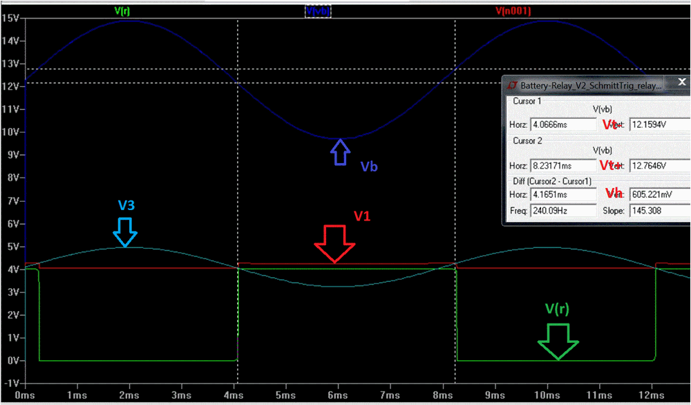
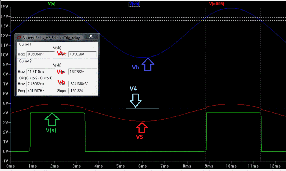
Jasper, The pot now works thanks. Comments on your circuit:- 1. The main issue I can see is that the 2 circuits are interlinked. 2. What is L1 used for? 3. D1 does not need to be a Schoktty diode, a silicon one such as the 1N4148 would suffice. 4. As I mentioned on my circuit, D2 will introduce a small error due to its thermal coefficient, ie. the voltage across it will vary a little with temp & thus alter your thresholds levels. The IC can be protected by other means. See my version below. I have not set the threshold levels to what you want, but that is easy. Set the negative going threshold first, then the Hystersis. I am currently working on a simpler solution using a CMOS Inverter (CD4049). I'll post it tomorrow. I don't have a model for the 4049 so I'll simulate it with an Op Amp. Someone from Wales told me (in electro-tech-online) that you can download the full set of 4000 series CMOS IC models, but I could not find the link he referred to. After lunch, I'll zip the .asc of my version in order to save you from having to draw it up. Len 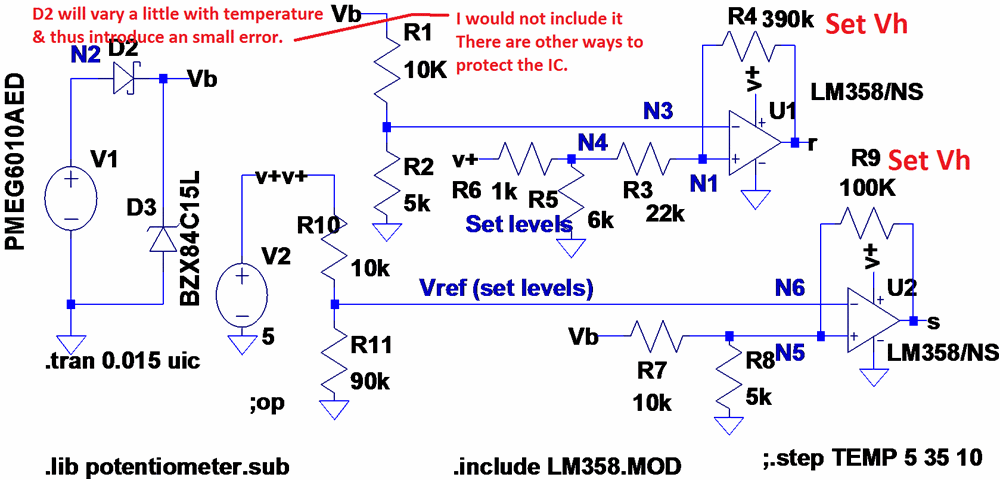
|
||||
| Warpspeed Guru Joined: 09/08/2007 Location: AustraliaPosts: 4406 |
Guys, The whole hysteresis thing is a an absolute nightmare to design with one chip if you want two very specific and precise voltage switching thresholds. But there is a solution. Use two voltage comparators and some logic gates. One comparator can be set with a potentiometer to a very precise "on" threshold voltage. The other comparator, quite independently, sets the "off" threshold voltage. Either switching threshold can be tweaked without effecting the other. Here is an application note of one way to do this. http://www.cypress.com/?docID=2239 The other way is to feed the two comparators into a pair of cross coupled NAND or NOR gates to form a set/reset flip flop. Cheers, Tony. |
||||
| SpmP Newbie Joined: 10/10/2010 Location: New ZealandPosts: 32 |
Thanks warpspeed, that was my original design for where I have a ~4V hysteresis. See schematic at the beginning of this post, but using opamps rather than comparators, and a latching relay instead of a sr flipflop. I had a version that had a discrete flip flop as well, thankefully I came across the method of latching relays 8) The hysteresis thing is looking good for 0.03V hysteresis tho 8) Cheers. |
||||
| SpmP Newbie Joined: 10/10/2010 Location: New ZealandPosts: 32 |
Heya Len here is the LTSpice cmos stuff. I basically agree with warpspeed. What reason is there in terms of the original brief (i.,e 20years+ operation etc) to _not_ do this and do something else? Cmos library info and the files for 74HCT 2012-05-04_144531_74HCT.zip |
||||
| larny Guru Joined: 31/10/2011 Location: AustraliaPosts: 346 |
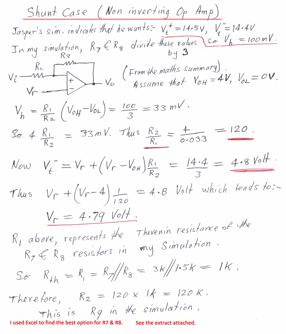
Jasper, Well I don't agree with warpspeed. If you follow the maths I posted in one of the previous posts, it is quite easy. I've re-posted the maths below for your & warpspeed's convenience. I'll do an example calculation & post it later. The esential point to note in the maths is that Vr is not in the formula for Vh, so you can set Vh independently of Vt-. Len 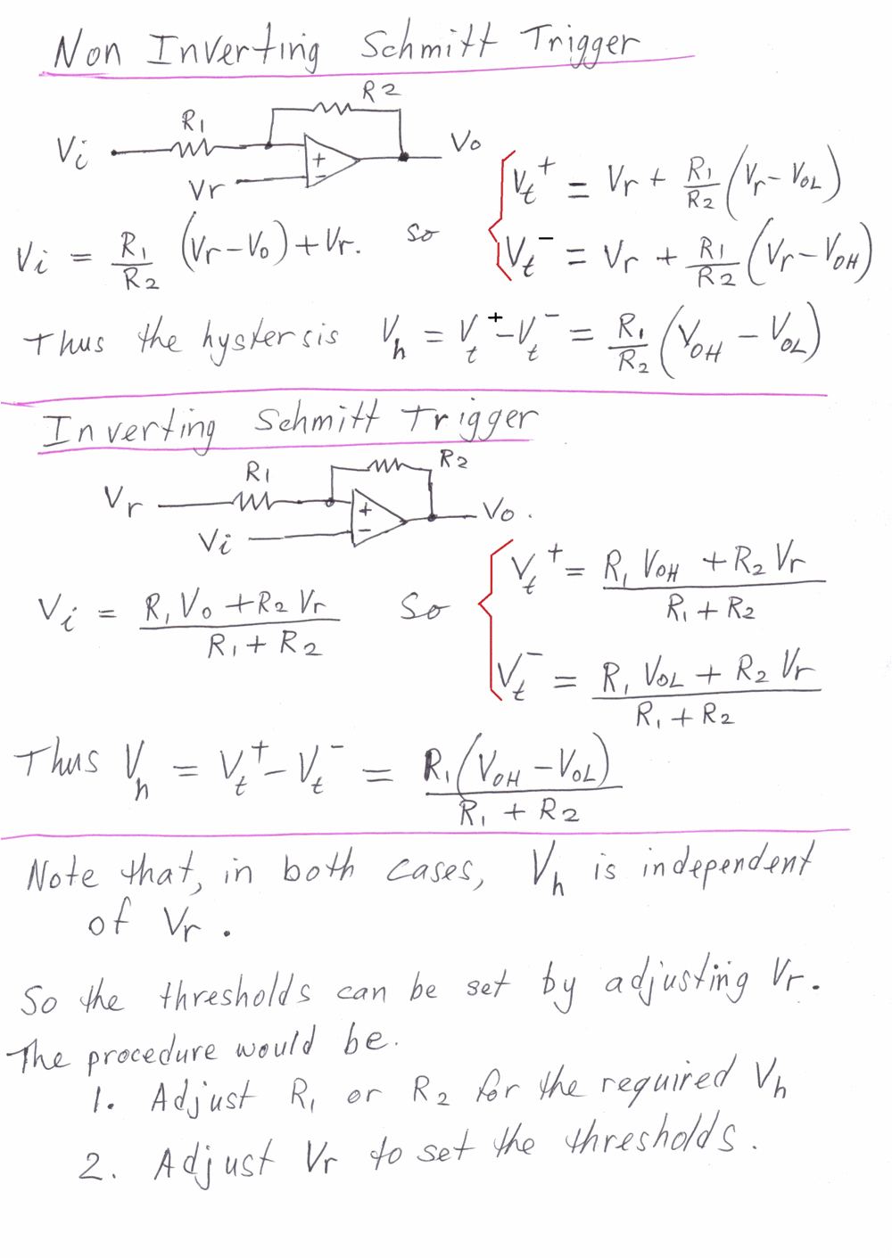
|
||||
| Warpspeed Guru Joined: 09/08/2007 Location: AustraliaPosts: 4406 |
I had never thought of using a latching relay. Should work very well, but with the single disadvantage that latching relays are fairly uncommon, and trying to find a suitable replacement many years later may present a bit of a challenge. As far as the maths go for single comparator hysteresis, sure it is possible, but you can end up requiring some really odd value resistor ratios which can be somewhat inconvenient. Fitting some trim potentiometers to it is not really an ideal solution either, because tweaking one threshold effects the other threshold. Initially adjusting it will drive you nuts. Far better to use two independent comparators if you want two independently adjustable and ACCURATE switching thresholds that are dead easy to set up very first attempt. Cheers, Tony. |
||||
| larny Guru Joined: 31/10/2011 Location: AustraliaPosts: 346 |
G'day warpspeed, He did not use a latching type relay. He used a normal relay which held via its own contact to another MOSFET which was turned on by the other Op Amp. See his early posts. No - the Vh is set first then Vt-. These are independent. And of course, Vt+ = Vt- + Vh. It will be clearer when I post the examples later. I have not looked at the circuit that you posted the URL for yet. I have to go out now so I'll do it & the examples later. len |
||||
| larny Guru Joined: 31/10/2011 Location: AustraliaPosts: 346 |
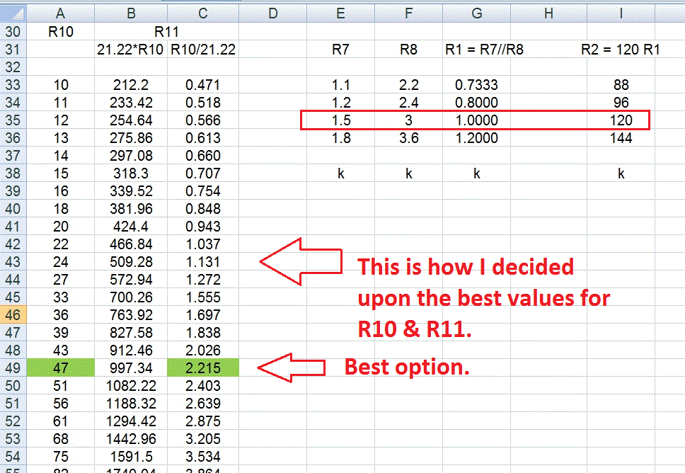
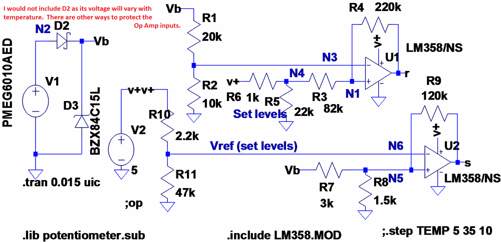
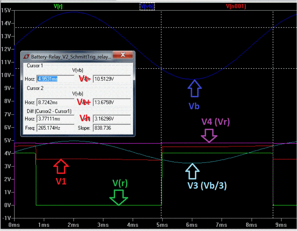
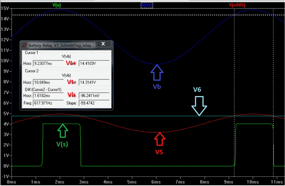
Jasper, Thanks for the links, I have downloaded the 4000 CMOS & the 74HCxxx files & will insert them into my LTspice folders later. I used your simulation to discover what threshold levels you want. I have done the maths and calculations accordingly (as below) & have used them in my latest simulation - attached below. I have included an extract from the Excel spreadsheet that I used to help with the calculations. Note that I accidentally transposed R10 & R11 in the spread sheet, but the calcs are correct. HOWEVER, I don't regard this as a practical circuit at this stage for several reasons such as:- 1. I have not considered the Opamp's offset. 2. The Voh level may vary with temperature. 3. The + & - inputs to the Opamps need to have approximately the same Thevenin resistances. 4. I would eliminate diode D2 and protect opamp inputs by different method. etc. I'm mainly concerned about the shunt case since the hysteresis is so small & is made even smaller by the voltage divider. So there is little margin for the effects of temperature changes & the fact that component values change a little as they age, etc. Some further thought needs to be put into this area. Warpspeed, Note that I was able to calculate the threshold levels & hysteresis such that there is no interaction between the settings. This is because the hysteresis does not depend upon the reference voltage Vr & because I designed the voltage divider formed by R5 and R6 such that its Thevenin resistance is much less than R3. The Thevenin resistance is the parallel combination of R5 & R6 so it is just below 1k. Therefore, any (small to medium) change to either R5 or R6 will have virtually no affect on the hysteresis. After doing the calculations, I transferred the values into the simulation & and the traces below are the result without any fiddling of values. Regardless of whether you are doing it by calculation or by adjusting potentiometers, the procedure is essentially the same:- 1. Set the hysteresis first 2. Then set one threshold by adjusting the reference voltage Vr. I suspect that part of your "hystersis nightmare" may have been due to the Thevenin resistance issue. Jasper, Tomorrow, time permitting, I will look at the suggestion by warpspeed, & if I don't like it, I'll investigate my ideas concerning the use of a CMOS inverter package. I'll post a simple explanation of Thevenin's Theorm and its relationship to McMillman's Theorem in another post. Len 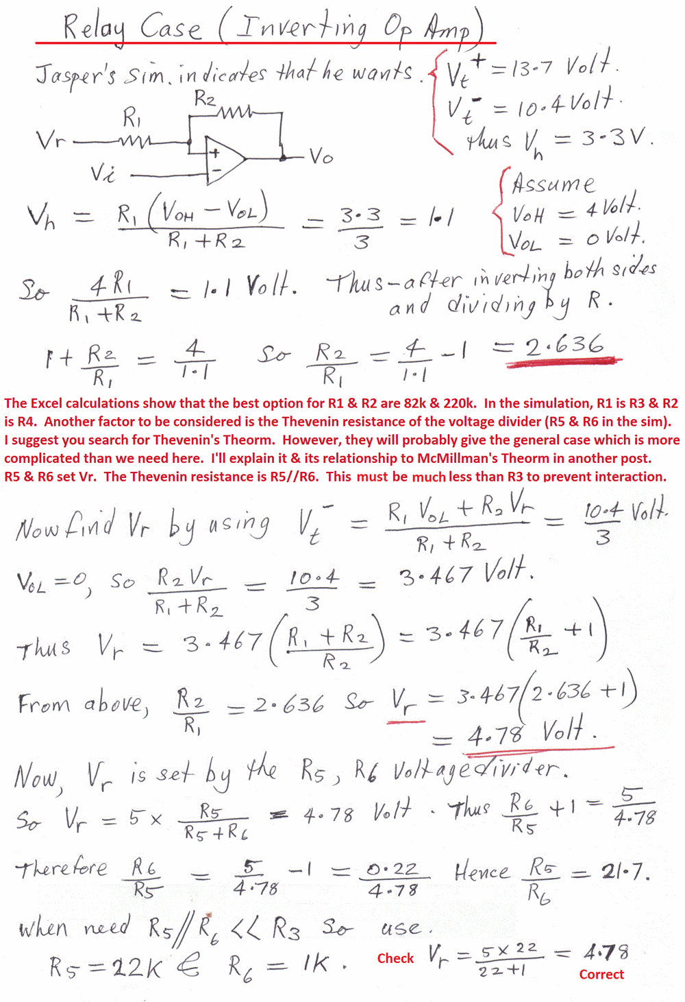
|
||||
| larny Guru Joined: 31/10/2011 Location: AustraliaPosts: 346 |
Warpspeed, I looked at the circuit you gave us the link to. I regard it as expensive & unnecessary. It uses 2 Op Amps & a Gate package to do what can be done with a single Op Amp (without any interaction issues) as I illustrated in my previous post. Len |
||||
| SpmP Newbie Joined: 10/10/2010 Location: New ZealandPosts: 32 |
Ok, I will build this and test it, esp. regarding setup. What is the better way of protecting the opamp and regulator? Thanks for the methodology, it is certainly instructive. I think that I would be using a 20K 15 turn pot for R5/R6, and a 50K 15 turn pot for R10/R11 For variable hysteresis I will need a 100K pot for R3. <You mentioned some time ago that you had a ee friend who disliked pots, even still, I need to use them here, so how can they be used to be most reliable. Out of habit when not used as a voltage divider, I always connect two of the legs. Is this good/bad etc? I havnt found much in my literature regarding this small point> Cheers. Jasper |
||||
| Warpspeed Guru Joined: 09/08/2007 Location: AustraliaPosts: 4406 |
So three pots required to adjust two voltage thresholds, that should be an interesting exercise. With the "complex and unnecessary" alternative, all you do is adjust the voltage right at one pot using a digital voltmeter to one required threshold voltage, and the voltage right on the other pot to the other required threshold voltage. Takes like thirty seconds to do, and it will be dead accurate very first attempt. With the "tweakable hysteresis" method, you have to keep manually swinging the input signal up and down to discover where it actually switches, while twiddling pots to get both thresholds exactly where you want to have them. Good luck with that.... Cheers, Tony. |
||||
| SpmP Newbie Joined: 10/10/2010 Location: New ZealandPosts: 32 |
Heya Tony, I understand, I have built the two pot circuit, and its great and easy, But, I am controlling two things here! 1) A relay to turn on and off a battery charger (Or a LVDS), so need two pots as per the original circuit, but this time to adjust the threshold and hysteresis 2) A FET to switch in the shunt load, again with one pot for threshold. So two different things, three pots. Also, this is different to what I have done before, and should be an interesting excersize to see in the real world how reliable this is. Reality will bear out its judgement. Please understand, my gut instinct sais 'go with the original...' But there are some real advantages to this setup, hence I am following this through to see if it works: * One dual opamp doing two tasks, related but different. Dual opamps more common than quad in terms of scavengability. * I can set the two thresholds independently so that Vshunt > Vbcharge. i.e if they were the same there is a possibility that the battery charger would never disengage as the shunt load would keep kicking in. * Low part count, no need for latching setup, doing away with one whole fet, not to mention that if I did it with the two Vrefs then I would need a quad opamp minimum. Also relay can be DPST (double for if its a LVDS) * The logic is such that to show the state of things with an LED has become simple. * To make an LVDS only one pot has to change, the hysteresis. (If at all) Ok so its not all bad. THE one bad is that hysteresis is a fairly academic idea when it comes to the nlow threshold, and will involve some T&E to get the right, granted. BUT this threshold is not super critical like it is for the upper threshold, and the shunt threshold. We dont want the batteries staying flat, so a low threshold of 11.2 or 11V is acceptable, as long as the batteries are getting charged when they are low tis all good, but must turn off before they go too high. So... to add to all this. In the last ZIP file I sent there was a schematic with the output circuitry, and some things have just occured to me that would be good to have feedback on. If I have those simple totem pole drivers on both fets (Currently only on the shunt fet as I anticipate high speed switching), then Can the top end of the totem pole be connected to v+ for say logic level fets, of Vb if logic level fets arnt available, s.t VGS is 10-14V... the can I is... Can VGS be greater than VDS, I am assuming it can, and will Vb on the tome pole top present an unacceptable voltage at the opamp outputs? The reason here is clearly the original brief, fixable with scavenged bits. From my simulations it looked like the totem pole wasn't driving the fet off hard, is this an error on my part or idiosyncrasy of the spice? In reality this circuit has worked well for me in the past. What ho! Warpspeed I appreciate your scepticism, and I hope not to be hearing I told you so. But until we try... Thanks all for your help, Indeed, I thought I was finished a week or so ago, but its all been worth it. Its a great process, community engineering! Esp. for me whose toes are barely wet. (I cant make it today, not enough pots 8) I will be building a 24V version for home, but its much of a muchness, only the two resistor dividers change. Cheers. |
||||
| Warpspeed Guru Joined: 09/08/2007 Location: AustraliaPosts: 4406 |
Yes, only constraint on Vg is max voltage, which is often +/-20v for power devices. FET will turn completely off below the gate threshold voltage, which may be around +3v to +4v for most devices. Just about any op amp or logic family will swing low enough to very easily turn any MOSFET completely off. Turning it "on" hard enough is sometimes a challenge, but "off" is always easy. There are always trade offs and compromises with designing anything like this, and there are a great many different ways to go about it, depending what you feel most comfortable with. It might even be argued(?) that a very low end microcontroller with an a/d converter and set points in software would be the simplest, most accurate and most flexible solution. Cheers, Tony. |
||||
| larny Guru Joined: 31/10/2011 Location: AustraliaPosts: 346 |
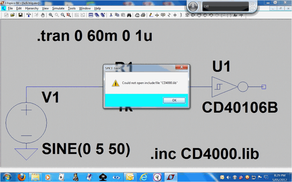
Jasper, You don't need any pots. Just set the resistors to the values I calculated. However, your Shunt ST has a very small hystersis (made worse due to the divide by 3 voltage divider) so it is going to be subject to component tolerances & temperature. That is why I'm still thinking about that one. I downloaded the CD4000.lib & CD4000.zip & inserted them into my LTSpice according to the instructions in the link you gave me. But it did not work & I don't know why. I did a simple sim of the 40106 Schmitt. See the windows below. Do you know what the problem might be? Len 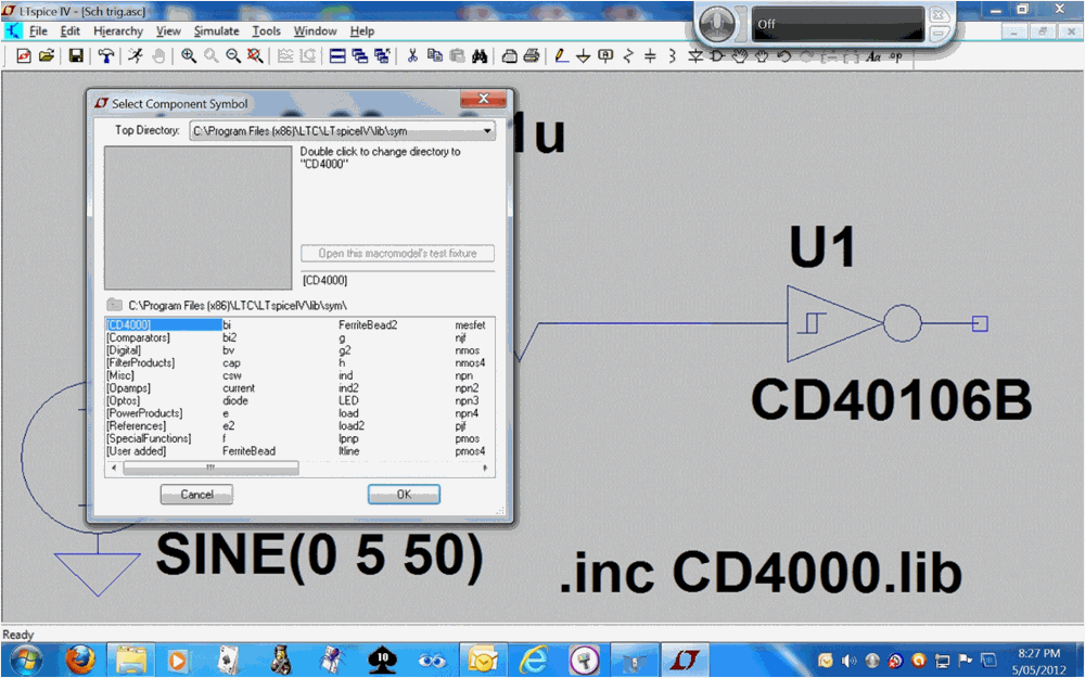
|
||||
| Warpspeed Guru Joined: 09/08/2007 Location: AustraliaPosts: 4406 |
Len, You do realise that the LM358 output cannot swing fully from rail to rail, and that the highest output voltage the LM358 output can reach is not at all well defined. It will be quite different for different LM358's from different manufacturers, different batches, and changes in temperature. Maximum capable upper voltage swing is a figure deliberately avoided on the LM358 data sheet for very good reason. They give a guaranteed upper swing, it will always go considerably higher than that, but by how much is a large unknown. That is going to directly effect the upper hysteresis threshold voltage, and toss a big unknown variable into any purely mathematical solution. Cheers, Tony. |
||||
| SpmP Newbie Joined: 10/10/2010 Location: New ZealandPosts: 32 |
Heya Tony, Considering this, can it be mitigated with a zener on the O/P? say 4.3V... But what is the order of magnitude of variance? A hysteresis of 0.1V would be good, but 0.3V wouldn't kill us. Take for example my 12V AGM's, float voltage is given as 2.23-2.27VPC, a difference of 0.24V across the whole battery, its not a big difference, granted. I will build it this afternoon, and use a pretty stuffed SLA as a load... I will let you know what I find. I will try with different IC's, and then in my toaster over, have a look around 40 degrees... Thanks again for the feedback. Len I will have a go with the spice thing tonight if I get some concentrated computer time. Jasper |
||||
| larny Guru Joined: 31/10/2011 Location: AustraliaPosts: 346 |
Tony, Agreed. One of the first steps I took at the outset was to check the LM358 Data Sheet. Jasper - see the attachment below. It is an extract from the Motorola DS. The Voh is as you said - unknown; however, it is good since the Vol is very low. The LTSpice assumes it is 4 Volt. It is also why I suggested a R2R Op Amp some time ago. However there are other ways to avoid this issue. There are also other issues. eg. I don't believe the LM358 is fast enough anyway. That is why I was thinking about using a CMOS inverter as a Schmitt Trigger. I have not fully explored that option yet. I have been trying to take Jasper through this in a step by step manner as I think he will learn more that way. Besides, I need the time to work through the large number of possibilities & issues. I have other things to do, so I can't do it all immediately. I will post a suggestion for him later re a DC-DC converter. If the supply voltage was say somewhere in the 25 ~ 30 Volt region, the threshold levels that he wants would then be in the Common Mode Range of the Op Amp & so he would not need to attenuate the signal. This attenuation is the major difficulty with his desire to make the hystersis 0.1 Volt for the Shunt case since it reduces the hystersis that the Op Amp must cope with. One possibile solution is to use 5V6 Zeners (5V6 since they have the least temperature coefficient) to shift the level so there is no attenuation But there is still the speed issue. For the CMOS solution, Vcc would have to limited to 15 Volt (or 18 Volt for some ICs) thus either level shifting and/or amplification would be necessary. Another possibilty I considered is the CMOS SChmitt Trigger, eg. the 40106, but the levels are fixed, so level shifting & amplification would be necessary. His 100 mV requirement is not an easy nut to crack. But we will get there. I'm interested in any suggestions that you may have. Len 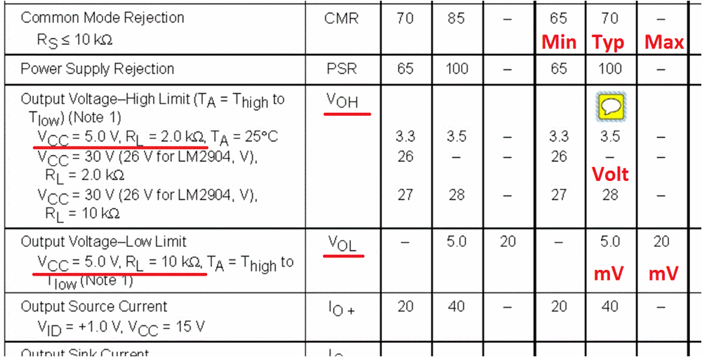 |
||||
| SpmP Newbie Joined: 10/10/2010 Location: New ZealandPosts: 32 |
Heya Tony, Considering this, can it be mitigated with a zener on the O/P? say 4.3V... But what is the order of magnitude of variance? A hysteresis of 0.1V would be good, but 0.3V wouldn't kill us. Take for example my 12V AGM's, float voltage is given as 2.23-2.27VPC, a difference of 0.24V across the whole battery, its not a big difference, granted. I will build it this afternoon, and use a pretty stuffed SLA as a load... I will let you know what I find. I will try with different IC's, and then in my toaster over, have a look around 40 degrees... Thanks again for the feedback. Len I will have a go with the spice thing tonight if I get some concentrated computer time. Jasper |
||||
| larny Guru Joined: 31/10/2011 Location: AustraliaPosts: 346 |
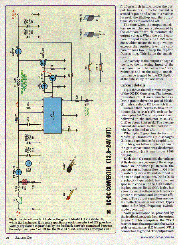
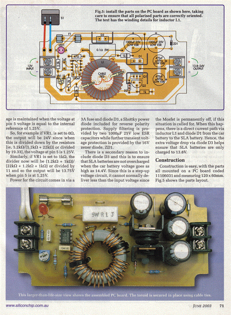
Jasper, I have attached below the scans of part of a Silicon Chip article of a DC to DC Converter. This can deliver a lot more power than you need, but that would not matter. This will allow us to operate the Op Amp at a much higher voltage, eg. 25 ~ 30 Volt. The advantages of this are:- 1. The thresholds you want for the Schmitt triggers would now be within the common mode range of the Op Amp. Therefore, we don’t need the attenuation so the Schmitt trigger would be designed for a hysteresis of 100 mV. This would provide a better margin for error. 2. Changes (due to temperature & device selection – See Tony’s post) to the high level output from the Op Amp, Voh, would be less significant since Vcc – Voh will be a smaller proportion Vcc. 3. The Op Amp may be faster. But see my comment below. Another way to do it would use a charge pump possibly based on a 555. This would roughly double your supply voltage from 12 volt to about 24 volt. I don’t know if the increased voltage will improve the speed. You could change the voltage supplied to the Op Amps in the simulation to 30 volt & see if the transitions are sharper. You certainly want the Op Amp outputs driving your MOSFETs to have short rise and fall times otherwise they are likely to overheat. Do you have an oscilloscope? Len 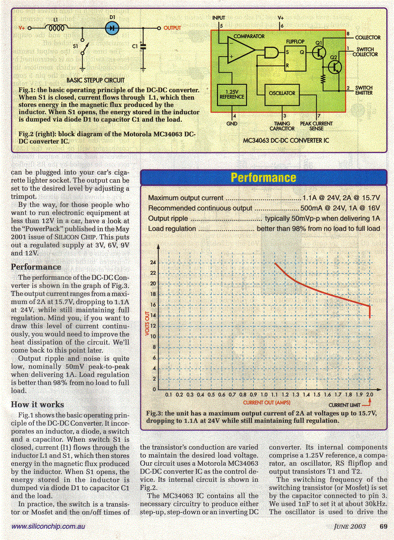
|
||||