
|

|
Forum Index : Electronics : NEW POWER LOGGER DESIGN
| Author | Message | ||||
| GWatPE Senior Member Joined: 01/09/2006 Location: AustraliaPosts: 2127 |
Hi AB, I don't doubt the theory, and appreciate different perspectives, but the cct that has been presented was distilled from application note designs similar to those you linked to above, by the way that when many of these were tested were found unsuitable for the low frequency problems that occur with a windmill application. The cct Pete has supplied includes a full wave precision rectifier-integrated AC current sensor, and has been tested on 50Hz mains, a F&P alternator, and an AxFx windmill, with good results, from 0.1A up to 25A on the AxFx windmill. RE the diode input protection to the micro and negative rails to op amps. The modern trend is towards single supply cct operation. Many of the interface problems with the micro are eliminated with a single supply cct. The resistor combo for voltage sensing I use as well, and works up to 68V without causing the micro protection diodes to conduct. By ths time the input power supply cap may be toast. The opto coupler is only connected to one phase, and the return path is back through the battery negative. There is no way that the chip negative is connected directly to the windmill AC, so there is no issue here. This uses one less RPM sense connecting wire, and will work on any AC wire, delta, or star. The optocoupler is an adaption of the RPM sense that I used on my own mill that is isolated and across a pair of phases. The connection of the optoLED return path to DC gnd is not a problem. The optocoupling gives protection to the darlington transistor[high gain component] without needing to use an op amp. This results in a good square wave output, from around 10rpm on my AxFx mill, to above 500rpm on a F&P. The cct presented is beyond theory now, has been tested on a variety of applications and the design was refined through many prototypes and this kit is the second attempt at getting an item for those not able to design their own, and the components have been selected so they now fit neatly in a small box, and should be no problem for many to build. There may be opportunity for improvements for those who have spent the time proving an alternative working example. This kit is not intended as a certified calibrated measurement device, but more for hobby windmill enthusiasts. To provide a higher level of precision and accuracy would probably move this to a commercial slant, and history has shown how this is accepted here. The companion windmill analyzer software is still not finished, and will be made available when completed. The piclog software packages will work with this kit. There may be some readers who have expressed interest in these kits who may go on to make improvements of their own. This is OK, but I feel that the intention of the kit is to allow many, to record their windmills and give more meaning to changes they make either positive or negative re windmill performance to these changes. Gordon. become more energy aware |
||||
Downwind Guru Joined: 09/09/2009 Location: AustraliaPosts: 2333 |
Hi AB, I respect your input. Firstly you need to close the books and put components to circuit board and then try it on a generator. You might just find as i did, all the good logic goes straight out the window. I have researched many of the links as you are, and tried some of the circuit designs that you refer to, they work well in practice and look good on the cro with a steady 50hz frequency, till you hook them to a generator with varying frequency and lots of line noise and all goes pear shape very quickly. The simple solution is to use a dedicated chip for this and not bother with all the other crap like charge pumps and +/- power supplies etc. This then makes it almost impossible for the home hobbiest to access the parts or even have the skills to assemble the board. As Gordon has addressed many of your comments there is little point in adding more. Until you have a working circuit tested and am able to offer it to others that has waited long enough for a suitable level kit allowing them to be able to construct and gather some relevant data, at a price within their budget, and not the size of a shoe box, i will continue with the present design. I do respect your engineering back ground advice, but until such time you have constructed and tested your circuit on a range of windmills as we have, and eliminated the problems that are encounted, i will consider it as theory unproven. There will always be a better mouse trap, it just needs someone to design it. Pete. Sometimes it just works |
||||
| SSW_squall Senior Member Joined: 20/03/2010 Location: AustraliaPosts: 111 |
Hi pete, No worries mate, i wasn't suggesting that you pull the pin on the design you've got going, ovbiously your confident that it will fly and that a really good thing!! Just maybe suggesting some ways for future reference it could be improve to be more flexible and robust. It has been mentioned that being able to log DC current/power would be a good thing and i certainly want to have this facility for my own system, so that should be on the cards for the logger version 2.0 I totally agree the theory is just that, until it's tested. Don't worry i do plenty of that (I have a sign on the door at work: FOR STRESS RELIEF - BANG HEAD HERE for added stress relief BANG SOMEONE ELSES HEAD HERE) However for me it's not good enough to just assert: this will definitly work OR that will never work. But to understand the mechanisms that enable a circuit (or anything else for that matter) to work the way it does or not as the case may be. That why i tried to spell out in some detail above exactly what was going on With that understanding any doubt that there's some black magic that means it won't work melts away... I will say that there IS something magical about all the parts of a design working the way they should together. I've already tried out the charge pump for generating the negative voltage on friday and it worked fine giving 4.3v into a 2.2k resistor which should be plenty for a LM358. Also just beacuse the circuit has some facility for calibration, doesn't mean the costs have to move into any sort of comercial league. Well if you don't mind paying for a 10 turn trimpot that is... Given the current transformers are less than $10 i'll order a couple and give it a red hot go... Regards AB Einstein: Everything should be made as simple as possible, but not one bit simpler |
||||
Downwind Guru Joined: 09/09/2009 Location: AustraliaPosts: 2333 |
Hi AB, I have a hole in the door from banging my head. 
Electronics is like that. Challenging. It was the low cost of the CT's that got me started on all this in the first place. The idea of a calibration pot is good, but i spent a lot of time getting pots out of the circuit and down to fixed components, so it was easier to set the circuit up for someone with limited knowledge and equipment. KISS theory. As you are using hydro i doubt you will have the varing of frequency that a windmill has, so it might be a little easier to tailor a circuit better for your needs, as your output will be more constant. As for DC amps the idea here is to add a sister board onto the spare I/O to read a shunt if needed. This is why i left the pin free so it could be adapted for any purpose. Im sure you will come up with a better mouse trap. Pete. Sometimes it just works |
||||
Downwind Guru Joined: 09/09/2009 Location: AustraliaPosts: 2333 |
WIRELESS LOGGER RECEIVER 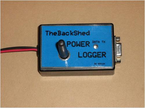
As there has been some interest with using the wireless module with the Power Logger board, so I put together a receiver circuit board. 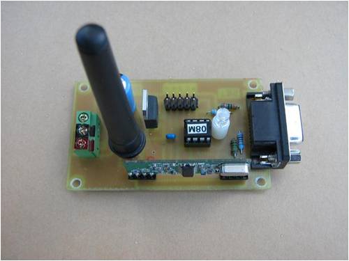
There is very little needed on the receiver board except for a 08m picaxe, serial connection, and voltage regulator, plus the 433mhz receiver module and antenna. It could easily be vero boarded. I have not pushed the use of the wireless function with the Power Logger as there is to many problems that might influence how well this will operate. Like the distance between TX & RX, (Transmitter and Receiver) what obstructions are in the signal path, the type and location of antenna used, interference from other transmitters in close range on 433mhz frequency, etc, etc…… It simply might not work well enough for your location. But for those willing to have a play with this, it is not very hard and not over expensive. You will need to be able to program the 2 picaxe’s and trouble shoot any transmitting problems etc. I do think it is a lot fun and a good learning excise to play with the wireless stuff, and you will soon realize how easy it is. BUT it has its limitations. There is several people on the forum that have used these wireless modules at varying degrees of success, that can always help out with questions. Transmitter fitted to power logger board 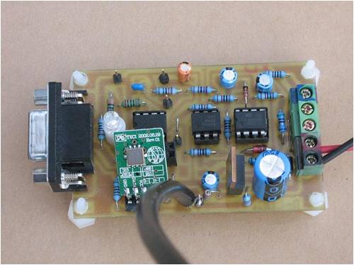
The antenna is rather important and can be a length of hookup wire 176mm long, this might vary slightly due to track length and other factors. Best results is with the antenna vertical, but this can be difficult in the wind or the wire type used. I have had good results extending the TX antenna 1-2 meters away from the circuit board with 50 ohm coaxal cable and then placing the antenna on the end of the coax. The coax outer shield needs to be connected to negative on the board and not used at the antenna end. The inner conductor is connected to the antenna out of the module 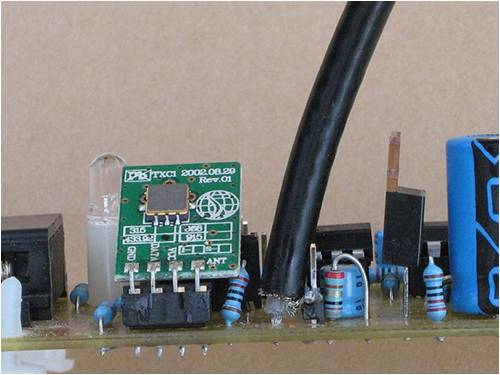
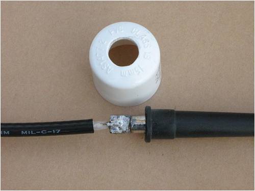
A piece of heatshrink tube acts as a strain relief to the cable 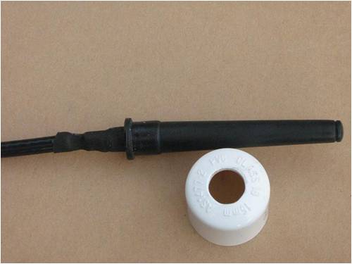
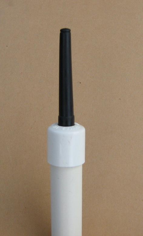
I also have had good results with little whip antennas to suit 433mhz, but it will all depend on the distance and what you have available. As any metal near the antenna can cause interference with the transmition, I used a length of 15mm PVC pipe and a cap to mount the antenna with. A 10mm hole in the cap allows the antenna to pull into tightly. A smear of silicon to the underside of the cap ensures a weather proof seal. 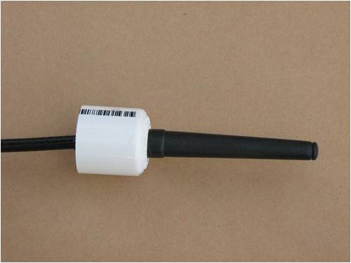
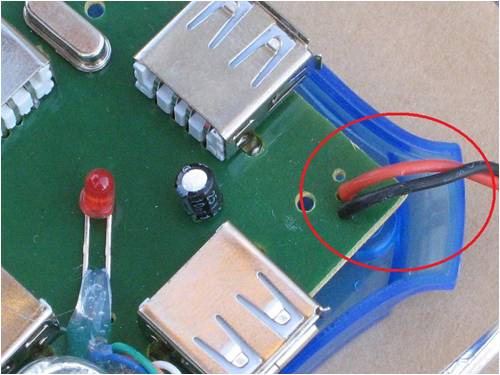
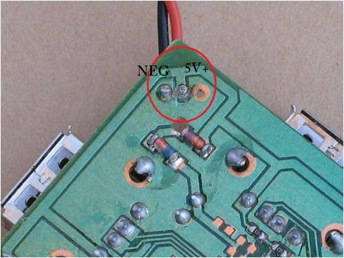
CHANGES TO SOURCE CODE The picaxe program will need to be changed to suit the wireless system. Firstly the TX program. There is several tricks that I use to get better data transfer with the 433mhz modules. 1. All data must be sent in ASCII code form. Not because they wont transmit otherwise, but because the picaxe can be instructed to read ASCII in. This gives a instant filter to a lot rubbish and interference that is otherwise picked up. Well it is still gets detected but its ignored by the picaxe receiver. 2. In the transmitting data string, there is a need to send some non ASCII data between each block of ASCII data, or the receiving picaxe will not always see the start and stop bit in the data string and will corrupt the data. 3. There should be a block of rubbish data sent before the actual ASCII data is started. This is because the receiver module has a sleep mode built in and if it don’t receives any data for a set time it goes to low power sleep mode, and needs to receiver data to wake up again. There is a slight delay with wakeup so by sending rubbish first up, its awake and ready for the actual data, when it is send. 4. It all sounds to hard right. Wrong its very easy all we do is send 10101010 or the hex number equivalent $aa Like this:- [code]serout 0, T2400,($aa,$aa,#volt, $aa, #Amp ,$aa ,#RPM, $aa,#Wind, $aa,#Check) [/code] So for the TX code all that is needed is to change the “sertxt” line of code for the one above in the current program. (source code) The RX end is a little different in code but rather small as it only needs to read the wireless data in, then check it and send it out the serial port. Again we need to read it back in ASCII code to filter any garbage we sent or is floating around. This is done like this :- [code]Serin RX ,T2400,#Volt,#Amp,#RPM,#Wind,#Check [/code] I should point out the $ sign in front of a digit or letter means Hex code in picaxe code. A # sign in front means ASCII code in picaxe code. Then we check the data to see if it is corrupted. As the value of Check should be the same as all the other 4 added together. We do this addition again and check it to match the value of Check, and if it do match then send the data out to the computer via serial. If it don’t match then the data was corrupted and its rejected and we take another read of new data, and so on till the data is valid. I will include a test program that can be loaded into the TX picaxe that will allow for the TX end to send a continuos data stream of 50Volt, 100AMP, 150RPM, 200Wind, 500Check This will allow the receiver program to be tested for communication with the Transmitter as in the case of no reception or corrupt data the RX led will not flash and will only flash if valid data is received. Gordon’s comm. Sniffer or using Picaxe Programming editor and press F8 the valid data can be seen on screen in its raw form. [code] ( [ <V> 50 </V > <I> 100 </I> <R> 150 </R> <W> 200 </R> <C> 500 </C>] ) [/code] A test done with this antenna setup and using 6m of connecting coaxal cable. I was able to receive data to 150m away, but it was intermittent. At around 50m the signal should be reasonable for reception. POWERING THE RX BOARD The receiver board can be powered off the usb power from the computer if desired, to save on a power supply needed. As the usb to serial cable don’t have the 5 volts connected to the serial pins, it requires an adaptor to pickup on the power from a usb socket. I had a cheap $2.50 4 way usb hub, that on closer inspection found it had unused holes in the board with 5v+ and – to them, and a place in the housing to allowed for the cable to come out through. Bonus. And I got 3 extra usb ports as well. Double Bonus. 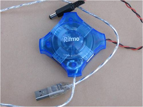
Some Notes:- If using the RX kit it is best to set the board up and get every thing working before fitting it to the box provided. The main reason for this is the antenna needs to be removed from the board and placed through the hole in the box before placing the board into the box. Then the antenna needs to be fed through the board and soldered into place with all assembled in the box. The board can not be removed again unless the antenna is unsoldered from the board. When using coaxal cable off the TX board you will need to make provisions to bring the cable out of the box as I have not allowed for this and don’t think it will fit through the grommet with all others wires. For an earth to solder the outer shield to, I used a header pin through the board and trimmed the outer shield back to only a few strands then soldered these to the header pin. It is important to keep the exposed inner conductor as short as possible to reduce possible interference. (this applies to both ends of the coaxal cable) It is worth loading the test program (TX end) when first testing the operation of the wireless modules. I find a 9 volt battery to power the receiver (RX) board good here as it allows you to walk around with the kit and see where and where not you have a signal. One of the most important parts is good clear transmitting of the signal or no matter what you do reception will be poor otherwise. PARTS LIST 1 x 10K resistor 1 x 1K resistor 1 x 22K resistor 1 x 330R resistor 1 x 180R resistor 1 x 220R resistor (for limiting resistor on the TX board) 1 x LED 1 x Diode - 1N4001 1 x LM-7805 voltage regulator 1 x 330uF x 25v capacitor 1 x 10⁴ (0.1uF) capacitor 3 x 8 pin IC sockets (2 need to be cut in half) 1 x 08M Picaxe 1 x D-9 female 90 degree com port socket 3 x terminal blocks for wire connections 1 set of 433mhz Transmitter and Receiver modules. 1 x small Jiffy box enclosure to fit it into. Test Program 2010-07-04_224642_TBS_Power_Logger_TX_tester.zip TX Program 2010-07-04_224830_TBS_Power_Logger_TX.zip RX Program 2010-07-04_224927_TBS_Power_Logger_RX.zip Circuit Layout 2010-07-04_225041_RX_Logger_board_Top_view.pdf PCB Artwork 2010-07-04_225241_LOGGER_RX_BOARD.zip Schematic 2010-07-04_225913_Schematic_RX_433mhz_Board.pdf Pete. Sometimes it just works |
||||
Downwind Guru Joined: 09/09/2009 Location: AustraliaPosts: 2333 |
As i had used a high voltage regulator in the circuit that might be hard to find, i checked the more common LM-317 adjustable voltage reg and found it is pin for pin compatable with the TL-783 that is used in the kits. For any logger that is to be used with a 12 or 24 volt system the LM-317 is a good choice as it will handle upto 40 volt on the input and well within the maxinum voltage range for 24 volt systems, but not suitable for 48 volt systems. Two resistors will need to be change for use of the LM-317. Resistors R14 and R15 on the schematic will need to be changed to... R14 will need to be 220 ohm and R15 will need to be 680 ohm Here is a new schematic with a foot note for the change needed with the use of the LM-317. Revised schematic. 2010-07-05_192216_POWER_LOGGER_SCHEMATIC.pdf Pete. Sometimes it just works |
||||
niall1 Senior Member Joined: 20/11/2008 Location: IrelandPosts: 331 |
hi Pete the detailed posts make great reading...its always nice looking at neat work on boards and drooling a bit as to how the thing works and was put together ... 
niall |
||||
| GWatPE Senior Member Joined: 01/09/2006 Location: AustraliaPosts: 2127 |
I have finally managed to get the windmill analyzer part of the power logger together. here is a link to the download file. 2010-07-16_235353_Windmill_Analyzer_DEMO.zip I have more info on the "just what to log" thread. logging at up to 60 readings/min is possible. This captures most windmill transients and can help give insight into windmill performance missed at slower rates. I have recorded at up to 3 readings/sec, but other chip constraints with RPM and windspeed make this impracticle, so I have restricted it to 1 sec for the demo. The log files are reduced to hourly, for logging intervals below 10 seconds. I am sure readers will quickly work out the setup and run menus and channel calibration aspects. Analyzing of existing piclog data is also possible. Gordon. become more energy aware |
||||
| SSW_squall Senior Member Joined: 20/03/2010 Location: AustraliaPosts: 111 |
Further to a few things discussed earlier in this thread... Ordered one of those current transformers, it's arrived OK and it looks good. Havn't tried it yet because i've been so busy doing the first production run of the KDSA subamp at work. Which brings me to some info that may be of some interest... As part of the KDSA (krix digital sub amp) project i've had to come up with a testing system that tests each PCB when it finishes the production process at Parketronics. Ensuring that the amp modules shipped to us have quality assurance. Basicaly this involves a test controller that inputs a test tone into the amp module at a defined level and looks for a given output at the loudspeaker leads. Which is then stepped down by a 100V line transformer and sampled to check that the signal path is working properly and the voltage gain is within limits. By checking a couple of spot frequencies at the -3dB points of the high pass and low pass filters, these can be verified as well. The test controller uses one of the signal processor boards, with auto sense turn on cirucit jury rigged to function as an AC voltmeter. Up until this point, for the purposes of turning on the sub when a signal is present, i had only been taking one sample of the precison half-wave recfitied signal and this seemed to worked fine. Giving some level of adjustment over the threshold at which the turn on would occured. When i tried this single sample system for accurately checking the gain i found the value was bouncing up and down by about 100 of 1024 (or 10% of the 10bit ADC) and this made setting a good pass window for the test all the more problematic. Jacked the Cro onto the output of the precision half-wave rectifier with ac coupling and of course there was about 100mV pk-pk ripple. Even with the 4.7k and 10uF cap that was providing some smoothing. Using a bigger time constant would reduce the ripple, but would also slow the response of the circuit. So i ended up writing some code that would take 12 samples over about 50 milliseconds that would average the ripple out. Actually 16bit addition of the 10bit adc samples followed by a 16bit division of the number of samples To get a good average these samples have to be taken over at least one cycle at the ripple frequency concerned. In this case 30Hz 1/F = T = 33ms This delivered a MUCH more stable picture of the AC voltage in question, reducing the variation to about 3 out of 1024 full scale or less than 1%. The power logger works in a similar way, sampling a rectified signal to obtain a DC level that represents an AC voltage or current in question. Hence it may be worth putting some code on the PICAXE to do some local averaging, such that when the logger is require to deliver a result to the PC it is more representative. RE: LM317 replacement for the TL783 You could use the LM317 on a 48V system with 2x 12V 1W zeners and a 100 Ohm resistor in series with the unregulated supply to blead off the extra voltage and keep the LM317 within it's 30V rating. On the PCB this could just be 2x spaces in a "U" that could be wire linked across the "U" for 12v or 24v opperation or could fit some zener's for higher system voltages. Just a few thoughts to keep the juices flowing AB PS: I should be doing a presentation to the Adelaide section of the AES (audio engineering society) on the KDSA project, sometime in September at our facility in Hackham. It may be an opportunity for a FEW people to come along and check out what we do demo the 4way cinema horn loudspeakers ect PM me if your interested... Einstein: Everything should be made as simple as possible, but not one bit simpler |
||||
Downwind Guru Joined: 09/09/2009 Location: AustraliaPosts: 2333 |
Hi AB, Well they say great minds think alike. In the picaxe prog i do 20 readings over around 40-50 mS for the amps input, i see no real reason to divide this in the picaxe before sending the data to the PC as the division can be done faster and more accurate in the PC. This value is then divided by 2 (in the picaxe) and added to the next 20 readings to give a running average, which also gives a more stable reading. With a windmill the time constant is forever changing and is difficult to get a fixed period to work with, so again it is an average period used. My testing found that a combination of 10k and 10uF filtering gave the best results from the ripple, i do agree this slowed the response a little but was deemed not so important in the overall outcome for this purpose. When tested against allergro sensors it proved to be equally as responsive with less sensor noise. With the LM-317 they have a max voltage input of 40 volts not 30, and we did discuss the use of a limiting resistor and zeners with a LM-7085, but a lot of power is lost in the resistor and this combination of input limiting is ok as long as the output current level requirements remains constant. If the load on the circuit changes this can alter the voltage a little, which is enough to effect the ADC readings as they are referenced to the supply voltage needing to be stable. As on the board a spare pinout is available with 5v+ and neg. supply, it was an unknown possible load that could be connected, that was not able to be factored into the power requirements. As i had access to the HV regs and it was easier to design using them, but for others copying the circuit and needing to use a LM-317 with 48v system, than the resistor and zener is a good idea to solve the problem, as long as you dont have any device varying in current load being powered by the reg. Thanks for your input AB. Pete. Sometimes it just works |
||||
| SSW_squall Senior Member Joined: 20/03/2010 Location: AustraliaPosts: 111 |
They do indead 
Doing the averaging on the PC's fine as long as the comms can keep up with the sampling... A moving or rolling average is better again, because it's always the most up to date average. Your right about the LM317 the rating is 40V (that's what happens when i do these posts late at night) although i'd probably want to stay closer to 30V to be conservative. But perhaps i didn't spell out what i had in mind with the zener diodes. I wasn't thinking of the typical shunt regulator, which is generally always how you see a zener diode used. And yes i agree this type of regulator does waste alot of power. But using them to simply drop some voltage, in a way thats not dependent on the current draw, which would be the case if a simple resistor was used. Actually some 9.1v 1W Zeners would be a better choice, this will drop almost 20v that won't change much with the current draw of the regulator. Zeners typically drop a abit more voltage than the nominal spec, especially as they warm up a little bit. 48 - 20 = 28V minus a few volts across the 100 Ohm resistor on the regulator input leaving approx 20V differential across the reg so it can do it's job. The max current output is determined by the power disipation of the zeners 1/9.1 = approx 100mA, although i'd always genereously derate the zeners by at least half especially in a high voltage regulator application. If more current is needed then just parallel a few zeners up... The 100Ohm resistor is to safe guard the zeners and limit the current when power is first applied. As the 470uF cap will draw a big gulp of current as the regulator attempts to charge it up and this could easily exceed the max current rating of the zeners. Also it would be highly recomended to have the reverse diode across the LM317 to stop it blowing up when power is switched off. Regards AB Einstein: Everything should be made as simple as possible, but not one bit simpler |
||||
| VK4AYQ Guru Joined: 02/12/2009 Location: AustraliaPosts: 2539 |
Hi Pete Just a point Im not clear on, when you say a 48 volt system the voltage of which can go to 60 volts during the charge cycle, is that still within the design parameters? All the best Bob Foolin Around |
||||
Downwind Guru Joined: 09/09/2009 Location: AustraliaPosts: 2333 |
Hi Bob Good question, the Vreg can handle up to 125 volt input, the filter cap across the input is rated to 63 volts so this limits the maximum input voltage to 60-63 volts, so the voltage divider for the voltage reading into the picaxe was calculated for a range of 60 volt full scale of the ADC reading. In simple terms the system input voltage was designed to work within 7 - 60 volt input. This should be within the maxiumn voltage reached for a 48 volt system when considering float and equilization charges reached under normal charaging operations. Short answer....... Yes! Pete. Sometimes it just works |
||||
Downwind Guru Joined: 09/09/2009 Location: AustraliaPosts: 2333 |
Hi AB A picture speaks a 1000 words. I see now what you mean with a "U" on the zeners. My gut feeling is there is a bug with this config, but until i isolate the bug i will not argue with your circuit. Over all it looks good but feel theres a ??. Thanks for the idea. Pete. Sometimes it just works |
||||
| SSW_squall Senior Member Joined: 20/03/2010 Location: AustraliaPosts: 111 |
No worries mate... I had thought about the 60V equalisation voltage, but this should be OK. As the LM317 reg will have approx 25V at it's input for the nominal 48V input voltage. If absolute max is input on the LM317 is 40V, that gives an additional 15V of head room which put us at 48 + 15 = 63V As long as the cable doesn't fall off the battery or something stupid it should be fine... AB Einstein: Everything should be made as simple as possible, but not one bit simpler |
||||
| SSW_squall Senior Member Joined: 20/03/2010 Location: AustraliaPosts: 111 |
Totally right pete, there is a bug i've drawn the zeners the wrong way around!! Stone the crows!!! It should look like this: Einstein: Everything should be made as simple as possible, but not one bit simpler |
||||
| arfarfarf Newbie Joined: 07/02/2012 Location: PhilippinesPosts: 2 |
hey pete!, im JC a undergrad student from the Philippines, i saw your post through google since i really need a energy logger to monitor my renewable energy thesis. your power logger and glen's piclog has been a huge help. but i was wondering if it was possible to use a different power supply to drive the circuit so that the logger will not consume any of the power on the battery of the piezoelectric. any help or reply would be much appreciated THANKS! |
||||
Downwind Guru Joined: 09/09/2009 Location: AustraliaPosts: 2333 |
There is no reason you can not use a different power supply as long as the negative from the power supply and the voltage being monitored are common together, although the only problem will be the voltage logged will be from the power supply not the source being logged. This can be changed by a small mod to the circuit, if you look just behind the terminals where all the wires connect to the board, there is a wire link from V+ to the 27K resistor, remove the wire link and connect the 27K resistor end of the link to the V+ of the source you wish to log. In reality though the small amount of power the circuit uses it is hardly worth the change, more power would be saved by removing the led as that alone uses more power than the complete circuit. Pete. Sometimes it just works |
||||
| arfarfarf Newbie Joined: 07/02/2012 Location: PhilippinesPosts: 2 |
thank you for that very quick reply! you really dont know how much this means to me. our deadline is in a week suddenly our thesis adviser drops us a challenge of logging the data! thank you so much! you rock! |
||||
Downwind Guru Joined: 09/09/2009 Location: AustraliaPosts: 2333 |
As time has progressed and off forum development of the logger, i would advise not to use the CT, as it is only good for AC current measurement and would recommend you look to the "Allegro" current sensors. Glenn has done a article on the front page about them and would be worth a read. Nothing like leaving things to the last minute to achive a project???? Pete. Sometimes it just works |
||||