
|

|
Forum Index : Solar : adding solar hot water plate collectors
| Author | Message | ||||
| KarlJ Guru Joined: 19/05/2008 Location: AustraliaPosts: 1178 |
OK here it is from someone who did EXACTLY what you are looking at doing here. 20 tubes, circulating pump and controller BTW link for prices is as good as my guy on ebay-well done. Tank -200L+ is pretty much mandatory or you WILL have problems as they can get real hot. PTR 850KPA at one end of the collector, burp valve the other end. Typically your storage unit will have three connections water in water out and one for the PTR valve. If you dont have a fancy three way fitting or cant use the one supplied (i couldnt due to the pressure dome inside the tank being in the way) plumb the return on the opposite side (T piece with the PTR) to the hot water outlet or at night you'll get cold water. Place a simple flat plate type one way valve $10-15 in the line going to the roof (cold side) this will prevent thermo cooling at night. pretty much done. Turn off the gas in Summer, Autumn and spring, turn it on to vacation or slightly higher for winter and it will work a treat. MUST have 600Kpa pressure limiting valve on the inlet to the HWS or you will have problems with any solar system as the temp fluctuations are greater thus thermal expansion will hit 800KPA no problems. MUST have a Tempering valve as one of the other guys said or you'll be burning yourself regularly. INsulate all the pipework with armourflex the thickest you can get, run you lines to the collector in 1/2" copper and use some old square downpipe to run the lagged pipes in. It may be UV stabilised (the armourflex) but the aussie sun still destroys it. Be careful with the tubes as they are fragile, pull the copper heat pipe out of the tube 4", lube up with transfer paste (will come with this) push it fully home into the manifold THEN insert the evacuated tube into the manifold. This is the trickey bit if you tap the end of the glass tube on the frame while wiggling it in it WILL break! Lastly for summertime hook up the dishwasher to HOT supply as you wont be able to use the hot water fast enough and dishwashers use 30-50L / load! any dramas give me a buzz Karl 0401627446 Luck favours the well prepared |
||||
MacGyver Guru Joined: 12/05/2009 Location: United StatesPosts: 1329 |
[Quote=rgormley]ok guys why the bends (dropped loops) on the inlet and outlet to the HWS ??? Yup! Those are heat traps. KarlJ brought up a very valid point; insulation. The classic difference between a "working" and a "non-working" solar application boils down to insulation. I like to use either "Rubatex" (brand name) or "T-cell" (Thermocell). Both degrade with UV, but if you work things right, changing insulation on the lines every couple of years is a snap. The T-cell comes with a pre-glued strip and all you do is peel the backing off both sides of the split in the insulation after it has been placed on the pipe and it's a done deal. When the temps get above 200 degrees, beach sand is the best insulator I've ever found. It's a little harder to work with, but 2" of the stuff will be air temperature on the surface, while beneath it can lie a receiver holding 400-degree hot oil! One last thing to remember: When you are using "soft" copper, it "work hardens" as it is unbent from the roll it comes on. This can be a good as well as a bad thing. Just be careful to make only one bend (plan ahead) on each piece and you'll have no trouble at all. Here in the US, we are required to use "no lead" solder on all domestic, potable water systems. If you're using it there too, remember it melts way hotter than 50/50. i use a paste "flux" (reducing agent) and MAPP gas in a turbo-torch and soft soldering is a breeze. Hope this helps you out. . . . . . Mac Nothing difficult is ever easy! Perhaps better stated in the words of Morgan Freeman, "Where there is no struggle, there is no progress!" Copeville, Texas |
||||
| rgormley Senior Member Joined: 22/02/2006 Location: AustraliaPosts: 245 |
Karl, Thanks for the info, PTR valves.... do i need two of them or just one (already have on the HWS) My exsisting dux Gas storage unit already has a PTR on it, (dont know what rating though??) will this suffice or should i also purchase a 600KPA for fitting to the collector manifold. can you eleaberate what a "burp" valve is.. i thought a PTR does this function? my HWS has 5 holes 1 hole for the PTR right hand side 2 inlet (bot) both left and right sides of HWS 2 outlet (top) both left and right side of HWS The right hand in/out connections are unused so this is where i wil connect the circ pump and tubes up to the collector The left hand side has all the cold water in hot out tempering valve, so wont touch this stuff. |
||||
MacGyver Guru Joined: 12/05/2009 Location: United StatesPosts: 1329 |
[Quote=rgormley]can you eleaberate what a "burp" valve is.. i thought a PTR does this function? A "burp" valve lets the air out of the system and is mounted at the highest point in the system. If you tamper with the tension in the little valve (shrader valve?) it can be used to re-introduce air if you are to drain the system using a bypass-valve arrangement. I'll try to find some commercial links with pictures for you to look at and insert them here using the "edit" feature if and when I find them. edit: This is a 'similar' product. I'll try to find a better example. It's also caused a purge valve. Here's a better example. It's the 11th item down the list. See the little valve that looks like the one on your tire? It's a "Shrader" valve, exactly the same. If you loosen the tension on it, it will let air back into the collector when the pressure inside decreases as in when you drain the panel. 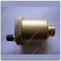
This little valve mounts in the vertical position, by the way. A "PTR" I'm assuming is a Pressure-Temperature Relief (valve) and in the USA they are set to open at 212 degrees F or 150 psig (pounds per square inch gauge). By the way, these valves are of the "single-use" design. Once they've popped (opened), it's time for a new one! They are a safety feature so if you should somehow have both an inlet and an outlet valve on your system and each is in a closed position while the heating source is on, they prevent your water heater from becoming a bomb. In all likelihood, in an over-pressure or over-temperature situation, there would be nothing more than a split in the tank or associated piping should the p/t valve fail or even not be installed. On the other hand, if there were air in the system, it really could "explode" and throw stuff all over creation! Like I said, it's a safety device. I once had a customer try to "help" me and thinking he was opening a valve on the outlet side of his gas-fired water heater, actually closed it before the tank had filled. He lit the thing and I caught on what had happened moments before it would have let off the t&p (as we call them) valve. By the way, the "working pressure" is far and above what you should be using. House pressure should be regulated between 55 and 80 psig. . . . . . Mac Nothing difficult is ever easy! Perhaps better stated in the words of Morgan Freeman, "Where there is no struggle, there is no progress!" Copeville, Texas |
||||
| rgormley Senior Member Joined: 22/02/2006 Location: AustraliaPosts: 245 |
to the people giving me a hand as i go , i thank you greatly!! 
Now a evacuated tubed orientation question. i do have a north facing bit of space where i can place the 15 tube frame, but the tube runs will be nearly 14 meters. or i can go on a west face an it will be around a 8 meter run. shorter runs So will the evac tubes work ok/ good enough from a sun strike point that comes from the side for say 1/3 of the day? tubes are 1980mm by 58mm type my crude dwg show my house the house is scewed of to the east a little, the pic is from google earth 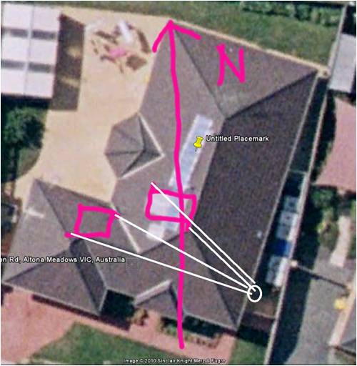
|
||||
Loomberah Regular Member Joined: 11/06/2008 Location: AustraliaPosts: 43 |
I'm running hot water through over 15m of 15mm pipe from my 30 tube system with no problems at all. It takes exactly 10 sec for the hot water to arrive from the tank. The water can be 90C at the end of that pipe, so losses are minimal Loomberah weather +solar&UV, astronomy, photography, organic farm |
||||
| rgormley Senior Member Joined: 22/02/2006 Location: AustraliaPosts: 245 |
what size tank are you using for your 30 tube unit? and what rise is the panel from the circulating pump? |
||||
| rgormley Senior Member Joined: 22/02/2006 Location: AustraliaPosts: 245 |
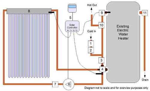
ok more questions my DUX tank has two inlets (left and right bott) and two outlets (left and right top) the left side connections are currently used. as for how i connect the solar collector, should i simply connect using the right hand side connection using the top as a input from the panel (hot) and bottom back to the panel (cold) as per first pic OR connect on the left side using a 4way conversion valve second pic 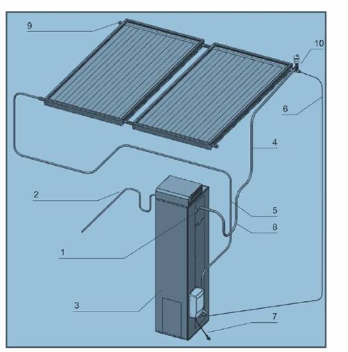
|
||||
Loomberah Regular Member Joined: 11/06/2008 Location: AustraliaPosts: 43 |
250litre, there is no circulating pump on the hot water. There is a circulating pump on the 78 tube hydronics heating system, but only to circulate the water through the radiators, the solar heating section is all thermosyphoning. The pump is about 4 or 5m below the tank. Loomberah weather +solar&UV, astronomy, photography, organic farm |
||||
| Chipboy Newbie Joined: 13/12/2006 Location: AustraliaPosts: 16 |
Google volts komissar and look at the manifold he has for this similar solution. Five way manifold at the bottom of the tank. All cold is drawn from the bottom and hot is returned to the bottom to rise as it does. Good luck. matt Wind wannabe |
||||
MacGyver Guru Joined: 12/05/2009 Location: United StatesPosts: 1329 |
Chipboy Any possibility of you posting a link to what you are talking about? I tried to google "volts komisar" and nothing looked like it had to do with solar; not to mention most of the stuff was some language I don't understand. To post a link, just click on the first picture of the tree and replace the URL information, then hit enter. Thanks. . . . . . Mac Nothing difficult is ever easy! Perhaps better stated in the words of Morgan Freeman, "Where there is no struggle, there is no progress!" Copeville, Texas |
||||
| rgormley Senior Member Joined: 22/02/2006 Location: AustraliaPosts: 245 |
yea i had the same problem, Google found many wonderful things including some things with animals +humans that looked very very wrong 
but no hits on solar stuff |
||||
| Chipboy Newbie Joined: 13/12/2006 Location: AustraliaPosts: 16 |
Sorry guys, I knew it by that name from years back, here is the link www.suburbia.com.au/~mickgg/K4/kernkraft.htm Matt Wind wannabe |
||||
| rgormley Senior Member Joined: 22/02/2006 Location: AustraliaPosts: 245 |
thanks for the link as it happens i did stumble on that web page in my hunt for info.. update: the IP53 rated double gpo is mounted the copper tubes have been run in the roof. more questions.... how about these as cheap pipe insulators? pool noodles 
not up near the collector but for say the straight runs in the roof? (i have a 2 x 14meter run in the roof) and they are a hell of a lot cheaper that armaflex Physical properties Depending on the crystallinity and molecular weight, a melting point and glass transition may or may not be observable. The temperature at which these occur varies strongly with the type of polyethylene. For common commercial grades of medium- and high-density polyethylene the melting point is typically in the range 120 to 130 °C (248 to 266 °F). The melting point for average, commercial, low-density polyethylene is typically 105 to 115 °C (221 to 239 °F). |
||||
| KarlJ Guru Joined: 19/05/2008 Location: AustraliaPosts: 1178 |
dont use the pool noodles they WILL melt! Luck favours the well prepared |
||||
| rgormley Senior Member Joined: 22/02/2006 Location: AustraliaPosts: 245 |
ok, as it happens i got a great price on 2 mtr lenghts of the armaflex 13mm wall 1/2 inch copper insulation, so wont be using the noodles....  |
||||
| rgormley Senior Member Joined: 22/02/2006 Location: AustraliaPosts: 245 |
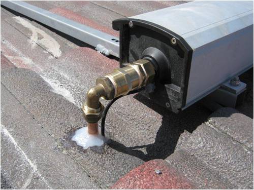
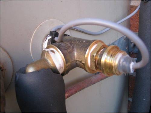
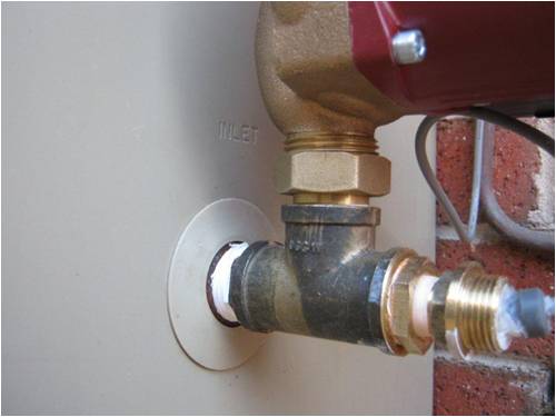
OK IT`s DONE!! this is a letter/update i sent to the supplier, it has a few updates and info.... Hi Alex, I will give you a breakdown in numbered form so you/we can expand if needed Also have attached a few photos, they are in reduced quality for transmission QA: is the pump good for a copper loop run of 30 meters (4.5 mtr rise) hope so�..??? QB: I can�t do a flow test (is this bad?) or not a problem, I presume the proof will be today, as the suns out and water temps are rising) QC: What Setting Should I have the pump on low/med/high ?? (remember it`s a 30 mtr copper run) 1: All 20 tubes arrived unbroken, there was a few side scratches from where something (fork lift blade) and hit and punctured the side of the box, but very minimal scratches. 2: Plastic Wrapping was open in a few places (could have let water in, if it rained) but no problem for my package, all dry and good 3: Package was asked to be signed for (my wife was home as it happens) signed on the hand held portable PC gizmo the couriers carry. 3: roughed the copper pipe in the roof last week ($85 for AS standard �� 0.91 mm soft annealed coils) The run is fairly long, at 15 mtrs from pump to manifold, hope the pump copes with this 4: insulation is Armaflex 1/2� by 13mm wall thickness (normal plumbers use 9mm wall) but I upped the thickness to the next size of 13mm wall ($3.41 per 2 mtr length) 5: run the external double gpo (looped from a nearby gpo in the bathroom) Clipsal ip53 rated GPO, 4 mts of electrical TPS2.5mm, and 1 junction box (parts only compliments of the sparky at my work) 6: bought the usual brass/copper fitting from a local plumbing wholesale store and bunnings 7: the drywell insert!!! What a hassle!! (lucky i`m a backyard engineer, read on !!) Not one of the 6 or so local plumbing stores had these things�. Some did not even know what I was talking about� So not be put off I went to bunnings to �make� a dry well insert, the guys at bunning`s understood what I wanted to buy or make but said there was nothing like that in the store. (millions of bits of stuff in a bunnings store, anything can be made!!) So i put my thinking cap on and made this�. Got a solid brass tap repair kit and pulled it apart, the insert has an internal 3/4 thread in it and the shaft diameter is around 12mm thick, so I measure the temp probe and core drilled the centre of the the tap repair shaft, reassembled the whole lot backwards into a � te piece inserting the temp probe in the newly drilled hole with some thermal grease and bingo one �drywell� insert, works like a charm!! Photos will explain this better, I should have taken photos and documented this but sorry did not. 8: connected all the plumbing fittings with some good quality pink boston tape (no it`s not gas tape) just slightly thicker plumbers water pipe tape. 9: bled the air out, 10 turned on the electrics on, unfortunately I can�t do a flow test (is this bad?) or not a problem, I presume the proof will be today, as the suns out and water temps are rising) 11: used the �test� mode to turn the pump on and all sounds ok, I can feel temps changing through the pipes so the pump must be flowing. 12: I am logging temps and time this morning (these are manifold temps) 13: 7:52am sun just on edge of roof line 14 Deg 7:58am sun just striking the top edge of manifold panel 15 Deg 8:17am sun 1/2 on sun 21 Deg 9:07am panel has full early morning sun 39 Deg Will keep you updated for a while as the day progreses Cheers, Richard 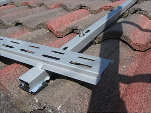
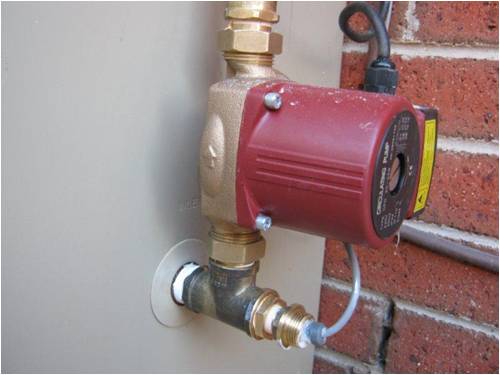
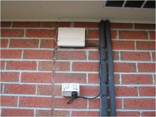
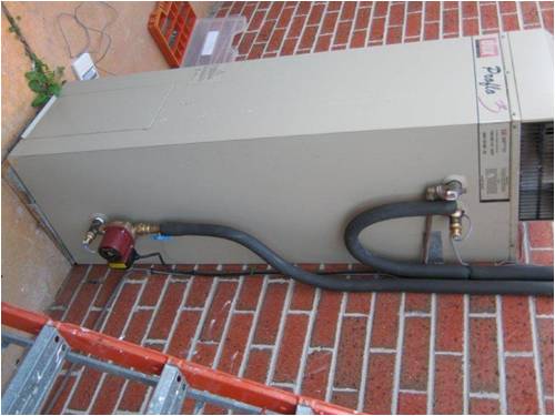
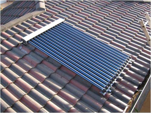
|
||||
| rgormley Senior Member Joined: 22/02/2006 Location: AustraliaPosts: 245 |
ok next hassle, i want/need/would like a way to shut the main gas feed to the burner (NOT THE PILOT) on a timed basis we dont need hot water from midnight to say 8am so why have HWS feathering the water temp on/of all night long..... i want to turn it off. In the way an electronic ignition system works. no power no gas. Turn the power back on and the ignition system turns on and gas flows/ignites. this can be controlled by a simple plug in timer OR is there a another way to turn of of the gas to ther HWS during the night DUX said they dont may retrofit electronic ignition kits for older heaters they are inbuilt on the new models only. SO the think cap has to be applied here.... some how fit a gas solenoid in the main burner line? (low voltage) ideas anyone? PS dont want to fit a another $900 odd dollars worth of instant heater and assoiated fittings..... |
||||
Downwind Guru Joined: 09/09/2009 Location: AustraliaPosts: 2333 |
Hi, The gas heater must have a thermostat to control the burner, is this a electric or mechanical thermostat. If its electric than the burner over ride would be rather simple. if its mechanical than the problem gets much bigger. Can you post some photos of the control gear for the gas system. Pete. Sometimes it just works |
||||
| rgormley Senior Member Joined: 22/02/2006 Location: AustraliaPosts: 245 |
it is a mechanical type (no electricity connected to it what so ever) dux proflo 135 litre gas storage will try to get some photos up when i get home tonight thanks... |
||||