| |
  Page 2 of 2 Page 2 of 2 |
| Author |
Message |
Bryan1

Guru

Joined: 22/02/2006
Location: AustraliaPosts: 2264 |
| Posted: 03:30am 09 Jul 2026 |
 Copy link to clipboard Copy link to clipboard |
 Print this post |
|
Well went for drive in this morning and got somemore 6AWG wire and wound the second choke 
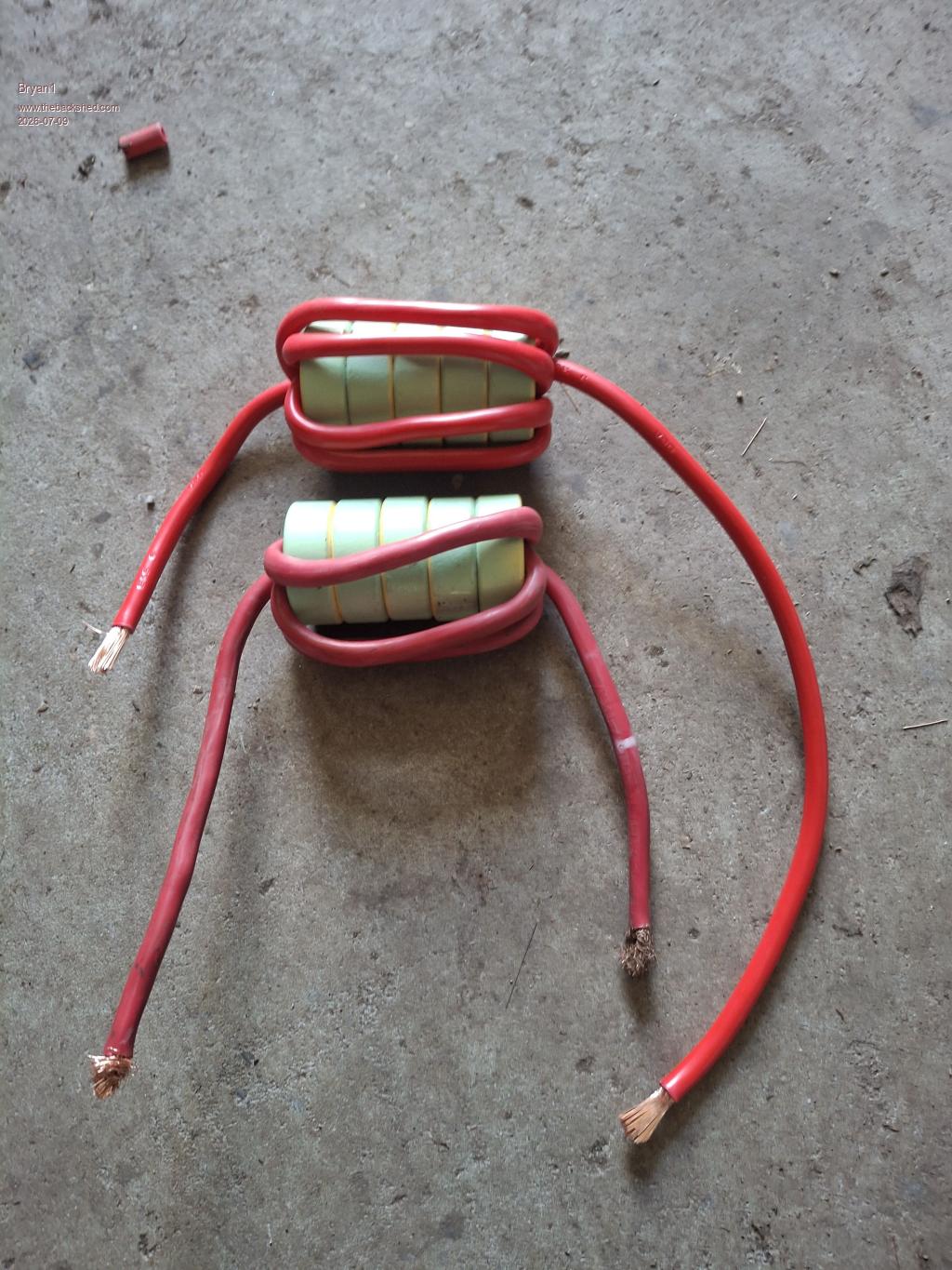
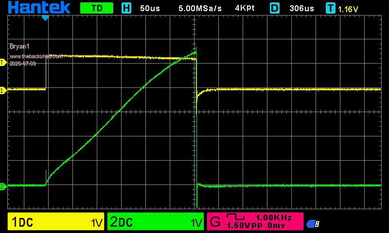
Now I retested the first choke
Then tested the one I just made
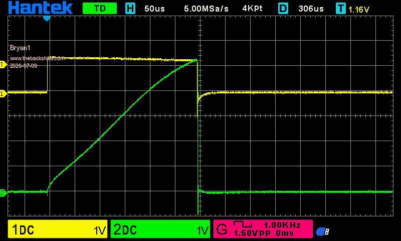
So for me it's close enough for a matched pair
Now to work out what to dremmel on the PCB so this project can move along.
Regards Bryan |
| |
KeepIS

Guru
Joined: 13/10/2014
Location: AustraliaPosts: 2265 |
| Posted: 04:08am 09 Jul 2026 |
Copy link to clipboard |
Print this post |
|
Bryan, just a few questions if I may to make sure everything is in order:
What is the power rating of your shunt resistor? Can you confirm that it still measures 0.02Ω? - assuming that is the value you used.
The shunt should ideally have very large bolt terminals right at the shunts resistive element, and virtually no lead length. IE: very heavy short copper to the FET, and the same to ground, and the Isense + and - leads taken from straight across the resistive elements terminals as close to the body as possible, otherwise the readings will be incorrect, especially for high current chokes.
NANO:Inverter V 8.4ks - Linux AvrDude GUI script V4.1 |
| |
Bryan1
Guru
Joined: 22/02/2006
Location: AustraliaPosts: 2264 |
| Posted: 04:32am 09 Jul 2026 |
Copy link to clipboard |
Print this post |
|
Keepis the 0.02 Ω shunt resistor is a 5 watt one and it's about 8mm away from the fet
Now measuring in circuit the measurement I got was 0.14Ω and I did measure the resistor before putting it in and it was 0.02Ω.
now I got my old fluke 865 out and the shunt resistor did measure 0.025Ω so I do believe that against this chinese scope DMM anyday.
Edited 2026-07-09 14:57 by Bryan1 |
| |
tinyt
Guru
Joined: 12/11/2017
Location: United StatesPosts: 564 |
| Posted: 01:06pm 09 Jul 2026 |
Copy link to clipboard |
Print this post |
|
Not sure if the color code here applies. |
| |
KeepIS
Guru
Joined: 13/10/2014
Location: AustraliaPosts: 2265 |
| Posted: 12:59am 10 Jul 2026 |
Copy link to clipboard |
Print this post |
|
A 0.02 Ω resistor with a 300A pulse has the potential for 1.8kW and 6 volts across that resistance.
The resistive "shunt voltage drop" must be read directly across the resistor terminals, or right at the body of the resistor if it has legs (through hole mounting).
You might need a real shunt when testing at very high choke currents?
I have never measured what a momentary, extremely high current Pulse-Shock does to various types of small resistors.
This is why I prefer a 500A (measures 0 to 700A) Hall Effect Current sensors instead of a large shunt, they actually cost less then most commercial resistive current shunts.
DC hall effect post
Possibly make a shunt, wound with some heavy single strand copper wire.
Most high current resistive shunts are usually made with strips of a low-resistance copper alloy, unfortunately this usually results in very low resistance values like 0.001 Ω to 0.00025 Ω.
If you are only looking at 30A to 70A chokes, what you have might work ok.
Perhaps someone has insight or has tested the effect in small wattage resistors at high pulse currents, as always, my thought radar might be glitching once again 
:
Edited 2026-07-10 13:31 by KeepIS
NANO:Inverter V 8.4ks - Linux AvrDude GUI script V4.1 |
| |
Solar Mike
Guru
Joined: 08/02/2015
Location: New ZealandPosts: 1252 |
| Posted: 03:31am 10 Jul 2026 |
Copy link to clipboard |
Print this post |
|
I have used these low inductance smd shunt resistors in the past, as the conductive edge is on the sides rather than the ends, they have high heat dissipation into the surrounding copper. Some of those hall affect types have a slow response, especially if you are using < 10us current pulses.
SMD Shunt
Its easier to wind on say 20-30 turns of lighter wire on your inductor, and do the saturation test with much less current; after, scale the reading for the actual turns you will be using.
Mike |
| |
KeepIS
Guru
Joined: 13/10/2014
Location: AustraliaPosts: 2265 |
| Posted: 03:38am 10 Jul 2026 |
Copy link to clipboard |
Print this post |
|
Thanks Mike, they look ideal, from the material used to the wide surface interface to a decent copper PCB track.
So good that I have ordered some for testing in the unit I'm about to build, 0.06 and 0.02, I can add a few in parallel if needed.
The Hall is @50A/uS, 10%-90%<7 us, I've tested against commercial resistive current shunts and only observed a slight lag in dual captured curves above 600A.
Edited 2026-07-10 13:50 by KeepIS
NANO:Inverter V 8.4ks - Linux AvrDude GUI script V4.1 |
| |
wiseguy

Guru
Joined: 21/06/2018
Location: AustraliaPosts: 1310 |
| Posted: 06:39am 11 Jul 2026 |
Copy link to clipboard |
Print this post |
|
The shunts of which I have used many hundreds in the past is the OAR series.
I like that they have graphs for surge ratings into the hundreds of Amps for 50mS.
The 0.005Ohm 1W parts I have used the most of, can withstand 600A for 50mSecs - I have never managed to open circuit one, the circuit breakers and fuses always open first
My Inductor tester uses a 3W 20mOhm part which the graph says withstands a 400A surge for 50 mSecs. Given that the test times are typically well below 1mSec, they are great in this application. In the tester I recently designed I use continuous sweep to obtain the right time and amplitude settings for the CRO. Then I set it for single sweep and press the test button briefly and now with minimal droop of the applied voltage I get a really nice frozen image of Inductor current. The tester is stand alone with a handful of components but uses the 2 x FET/ 2 x Diode arrangement that returns inductor stored current back to the supply rails.
I like this arrangement as you only need to supply the circuits losses and for an average test current of 0.5-1A I can see inductor currents to hundreds of Amps with a single supply and Bus capacitor typically 2,200uF - 4,700uF.
Shunt data is here:
OAR Data.pdf
Edited 2026-07-11 16:42 by wiseguy
If at first you dont succeed, I suggest you avoid sky diving....
Cheers Mike |
| |
KeepIS
Guru
Joined: 13/10/2014
Location: AustraliaPosts: 2265 |
| Posted: 09:25am 11 Jul 2026 |
Copy link to clipboard |
Print this post |
|
Thanks for the data sheet and confirming that they work in this situation.
When I was getting a few of the SMD shunts, I came across some small copper PCB current shunts, rated form 40A to 400A, which would be a continuous rating from the limited data I saw, and very low cost as well, the resistance is low though, typical 75 mV at rated current, so a bit under 002 Ω for the 40A, the 40A unit should handle a pulse of 500A, so I grabbed a packet of those as well to play with, knowing the low R would result in more noise, especially at low currents.
If the units I purchased fail, or give inconsistent results, we know the OAR shunts work.
BTW That design of yours sounds very nice
.
Edited 2026-07-11 19:30 by KeepIS
NANO:Inverter V 8.4ks - Linux AvrDude GUI script V4.1 |
| |
tinyt
Guru
Joined: 12/11/2017
Location: United StatesPosts: 564 |
| Posted: 02:39am 12 Jul 2026 |
Copy link to clipboard |
Print this post |
|
For what it is worth, just sharing my inductor testing in another forum:
Test start.
Final test results.
Note that the scope I used allows saving readings in spreadsheet format.
Edited 2026-07-12 12:39 by tinyt |
| |
KeepIS
Guru
Joined: 13/10/2014
Location: AustraliaPosts: 2265 |
| Posted: 08:51am 13 Jul 2026 |
Copy link to clipboard |
Print this post |
|
Hi tinyt, interesting read, things have changes a bit now, however I do remember when you posted the results of the china choke you bought in my original thread, it's the same as the one I bought and tested, as you also found, they were not what they claimed, the inductance was close in my case, 37.54uH @ 10kHz, but not capable of 200A with sufficient inductance left
:
Edited 2026-07-13 18:51 by KeepIS
NANO:Inverter V 8.4ks - Linux AvrDude GUI script V4.1 |
| |
| |
Page 2 of 2 |

 Notice. New forum software under development. It's going to miss a few functions and look a bit ugly for a while, but I'm working on it full time now as the old forum was too unstable. Couple days, all good. If you notice any issues, please contact me.