|

|
Forum Index : Electronics : A new controller circuit
| Author | Message | ||||
| GWatPE Senior Member Joined: 01/09/2006 Location: AustraliaPosts: 2127 |
Hi Vasi, all of the picaxe projects I have, include the programming components, including the 3pin header for comms. The 3 extra resistors are really nothing extra. The regulator controller I have designed for the skystream windmill has a single pcb. I have trialled at least 100 different ways of battery regulation, with only mods to the program. I have gone from the simplest ON/OFF control, to complex frequency measurements with proportional loading. The picaxe certainly allows a rapid development of ideas, without the need for a soldering iron. The proto board has to be pretty good design to allow this though. My proto board only required a wire link to be replaced by a track, from the original design, to the production unit. I have also made a tiny pcb, with an 8pin dip layout for new designs. This has the built in programming port as well. I add this board layout to any pcb production runs, so I have some spares around. I can use the small board as a plugin component, so the same chip can be used in many different applications. Very handy. I have also made a proto board for the 28X2, with onboard program port, Vcc regulator, bypassing caps with ADC's and output indicators etc etc. PWM is still an area that dedicated analogue seems to still rule. Gordon. become more energy aware |
||||
| Gizmo Admin Group Joined: 05/06/2004 Location: AustraliaPosts: 5078 |
I've made a few changes to the controller. I gave up on the pre adjust idea, you will need a variable power source to calibrate it. 
It works fine as a easy to set up windmill controller, and can be used as a shunt or diversion controller. This one is set up for 12v, the trimpots let you adjust between 11v and 16v, more than enough range for a 12v battery. I'll put a web page about the controller on the website in a few days, with modifications for 24v and 48v operation. I also have a veroboard layout. The same circuit could also be used for solar and as a low voltage cut out. Glenn The best time to plant a tree was twenty years ago, the second best time is right now. JAQ |
||||
| vasi Guru Joined: 23/03/2007 Location: RomaniaPosts: 1697 |
Nice schematic and easy to obtain components (no exotic parts). I prefer it agains my old oamp controller (I think I will dismantle it). Thank you Glenn. Vasi Hobbit name: Togo Toadfoot of Frogmorton Elvish name: Mablung Miriel Beyound Arduino Lang |
||||
| herbnz Senior Member Joined: 18/02/2007 Location: New ZealandPosts: 258 |
Hi I find dump control circuits that switch between two voltage levels in practice take to much charge out of the batteries at the levels they have to be set to avoid rapid switching due to voltage drop in the batteries as load is applied. I whether using PLC's or hardwired ccts detect the battery voltage I want to dump then dump for 10sec-30 sec or if battery voltage does not fall dump until it does then reset and monitor again. It means you are only taking the top charge off not lowing the charged state. Hard wired ccts very simple just a zener, 1 opp amp,one timmer, I use a commercial timer as I have a heap of Omron timers that fall off a truck, but a simple 555 ic could be used. Will try to post a circuit that has evolved for me will need to take pic of a hand drawing dont know how to do fancy ccts I see on here. That is if anyone is interested. Herb |
||||
| vasi Guru Joined: 23/03/2007 Location: RomaniaPosts: 1697 |
I am! Please Herb, post it! Hobbit name: Togo Toadfoot of Frogmorton Elvish name: Mablung Miriel Beyound Arduino Lang |
||||
| Gizmo Admin Group Joined: 05/06/2004 Location: AustraliaPosts: 5078 |
I've put the controller web page together and online, its at http://www.thebackshed.com/Windmill/articles/TL084-Controlle r.asp I'll put together a 48 volt version in time. Glenn The best time to plant a tree was twenty years ago, the second best time is right now. JAQ |
||||
| fgibbs56 Newbie Joined: 22/11/2009 Location: CanadaPosts: 3 |
I've been reading the forums here for some time, and have been looking into building this controller for a 48V system. I can build a system given the schematics, however, was wondering if your 48V system have been completed or not. I would like to build it as a temporary measure before working on a Picaxe version for 48V. Thanks for any help, and for all the help so far. |
||||
Downwind Guru Joined: 09/09/2009 Location: AustraliaPosts: 2333 |
fgibbs56 What circuit are you referring to for the controller?. I would think either the picaxe one or the opamp one would be ok with the v-reg changed to a suitable reg to handle the higher input voltage and a handfull of resistors changed and the relay. The picaxe would need some code values changed to suit. Gizmo or others may have done this already and i will wait to see what they have to say before commenting further. Pete. Sometimes it just works |
||||
| fgibbs56 Newbie Joined: 22/11/2009 Location: CanadaPosts: 3 |
Downwind Sorry about that, for the schematic for the controller based on the TL084 ( http://www.thebackshed.com/Windmill/articles/TL084-Controlle r.asp ) I would need to change the relay and use a larger resistor value at R1 and change the 7808 to something that could handle 48V? Thanks |
||||
| Dinges Senior Member Joined: 04/01/2008 Location: AlbaniaPosts: 510 |
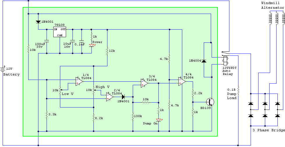
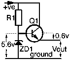
Clickable link to story/schematic: http://www.thebackshed.com/Windmill/articles/TL084-Controlle r.asp 1) The 7808 can't take more than 37V input, so 48V (and probably getting up to 60V) would destroy the voltage regulator. You'd need to replace it with a simple zener regulator (8V2 zener, transistor). Not sure but doubt the rest of the circuit draws more than 20-25mA, so could be relatively light-duty zener/transistor voltage regulator. Maybe make it a 12V regulator and put it in front of the 7808, so you'd still get the accurate voltage regulation of the 7808? Example of a generic zener/transistor regulator: http://www.satcure-focus.com/tutor/page5.htm 
2) The relay needs to be one with a 48V coil. 3) R1 needs to be increased to double the value for 24V, i.e. R1=47k 4) All electrolytics (esp. the 100uF one) need to be of adequate voltage. 5) The BD139 has a Vceo=80V http://www.datasheetcatalog.org/datasheet/SGSThomsonMicroele ctronics/mXvrwxu.pdf) ; the BD139 will be (barely) adequate at 48-60V, but leaves you with a very small safety margin. I'd replace it with something of higher voltage rating, just to be on the safe side. Had a quick look, the BD239C (C!) has a Vceo=100V. Any NPN transistor of Vceo > 100V and Ic > 1.5A (depends on the current the relais draws!) should be fine. If I had to build it for 48V, I think I'd leave the schematic exactly as is (except R1, which should be 47k), and insert a zener voltage regulator of, say, 12-15V in front of the 7808 (tap input voltage for the zener regulator at the junction of R1 & 1N4004; output voltage of zener regulator goes to input of the 7808; also make sure the coil of the relay is still connected directly to the input diode/R1, i.e. coil should be 'in front' of the zener regulator). Replace the BD139 with something suitable for higher voltage, and presto. You may want to search this board too, I vaguely recall this exact same question being asked a few months ago. Not 100% sure though. Peter. |
||||
| Janne Senior Member Joined: 20/06/2008 Location: FinlandPosts: 121 |
The AD8214 looks something, that could work for a 48V dump load.(assuming one can handle the smd package) The maximum operating voltage of 65V would be just enough. The current output should be suitable for driving a relay with npn transistor.. It should not take too many extra components, if one could settle on a simple on / off controller with hysteresis. Link for the manufacturer's web page If at first you don't succeed, try again. My projects |
||||
Downwind Guru Joined: 09/09/2009 Location: AustraliaPosts: 2333 |
The TL783 is a good high volt reg and will handle 125 volt input and adjustable down to 1.25 volts out at a max of 700mA. They do run rather hot and need a good heatsink. I have used many of these and never had a problem. If anyone has trouble finding the TL783 than let me know as i have a heap of them. Pete. Sometimes it just works |
||||
| GWatPE Senior Member Joined: 01/09/2006 Location: AustraliaPosts: 2127 |
I am testing a new windmill shutdown protection unit. Here is a pic. This unit is powered from and protects a 48V battery system. This is a commisioned unit, and the relay was requested to be operated at 64V and this is programmable anywhere in the range of 59-65V. The relay is released at 57V, but could be programmed for any voltage 48-58V. The relay was chosen for 48V operation, but a 24V relay could be used on a 24V system, and the voltages reprogrammed to suit. The control module will work from 15V to 65V, so would not be suitable for a 12V system without mods. I took the liberty of designing with a DC-DC converter with a simple pre regulator. There is a simple picaxe micro, with voltage sensing, driving a mosfet, that drives the relay. There is some hysterysis and timing involved. The relay gives full isolation, so the AC can be controlled, pre rectifiers, to give the highest braking ability. I will be looking at a frequency sensed option, that will give overspeed windmill protection, as well as battery protection. The component count is 10 for this arrangement [including micro programming port & mosfet], and the power is around 0.25W for the controller on 48V system [all the time from the battery], and 0.2A for the relay when operated. This could operate a diversion load, but is intended to shutdown the windmill. Gordon. become more energy aware |
||||
| fgibbs56 Newbie Joined: 22/11/2009 Location: CanadaPosts: 3 |
Thanks for all the suggestions, I will work on it over the winter here and test using variable DC source to see how well it will works. The windmill will get shut down for the winter, as there had been trouble last year do to excessive freezing rain weighing it dowm. I had ajusted all the components to 100V+ but was not sure on the regulator, the Zener sounds good, but I will maybe test a few different ideas around. I will update as I get more done. Thanks again. |
||||
| jjbob27 Newbie Joined: 13/10/2011 Location: New ZealandPosts: 4 |
Hey Gizmo, I'm a newbie here that tried and was able to built the controller that you designed. Was just wondering if you could hand me some of the calculations done for the op amp circuit? I'm trying to learn what kind of exact circuit is being used to control the high and low voltage setting and the 2 stage op amps after that ie Inverting, non inverting etc. Thanks, Joseph |
||||
| Gizmo Admin Group Joined: 05/06/2004 Location: AustraliaPosts: 5078 |
Hi Joseph I used a circuit simulator to help me with that circuit. Electronic Work Bench 2000 from memory. These days I hear LTSpice is pretty good, and free. http://www.linear.com/designtools/software/ There are a few good web sites about op-amps. Google op amp tutorial Glenn The best time to plant a tree was twenty years ago, the second best time is right now. JAQ |
||||
| powerednut Senior Member Joined: 09/12/2009 Location: AustraliaPosts: 221 |
Hi Joseph, This quick reference may be of assistance to you: analog devices op amp quick reference wall chart if you want a quick circuit simulator to play with a circuit, without getting into too much detail (essentially to give you an idea of how things are working) then falstad's circuit simulator may be of use: falstad circuit simulator The first two op amps (from the left) are acting as voltage comparators. A voltage comparator will compare to voltages and then produce an output voltage to indicate which is the greater of the two voltages. For the first comparator (again from the left) the voltages being compared are the battery voltage, through the 10k (R1) and 3.3k voltage divider which will have an output of, roughly, battery voltage/4 (so if your battery voltage is 12V, you'll get 3V at the junction of the 2 resistors). The other voltage compared is the reference voltage, which is set through the voltage divider formed by the 12k resistor (R2), the 10K variable resitor and the 8.2k resistor. This divider will have an output range of approx 2.1V to 4.8V. If this reference voltage is higher than the battery/4 voltage then the output of the op amp will be the same as the op amp's supply voltage. If the reference is less than batt/4 voltage then the op amp output will be 0V. The same logic follows for the 2nd op amp. Hope that helps. |
||||
Doug Regular Member Joined: 11/05/2010 Location: New ZealandPosts: 41 |
Hi all Here's a link to a 555 timer chip based charge controller I found. 555 charge controller Doug May The Power Be With You |
||||
| larny Guru Joined: 31/10/2011 Location: AustraliaPosts: 346 |
I joined this forum today, and found this thread of interest. I'm a retired electronics engineer & have had quite a bit of design experience. So I'm happy to help you if you need it. What is the current state of play? Are you still looking for a solution? Or have you found one? Len |
||||
| larny Guru Joined: 31/10/2011 Location: AustraliaPosts: 346 |
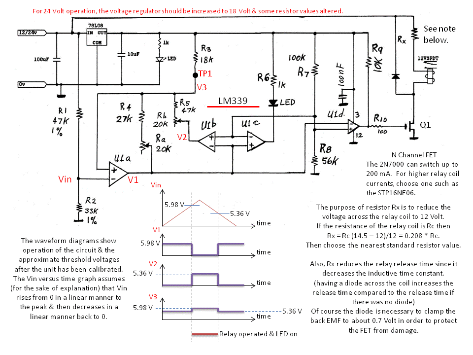
I have designed a controller circuit that I believe meets Gizmo's criteria stated in the first post. I don't have a windmill, so I have not built & tested the circuit. However, I've been an electronics engineer for more years than I care to remember & most of my designs work as drawn, the rest after minor corrections due to something I missed. So if anyone needs advice on how to modify the circuit for 24 or 48 Volt operation or has any problems, just let me know. Len 
Circuit description. The LM 339 is a quad voltage comparator with open collector outputs. Comparator U1a is configured as a Schmitt Trigger; it has hysteresis due to positive feedback via Ra and R4. The positive going threshold is set by R5 and Rb (the output of U1b is low because Vin is below the threshold since the output of the U1a is open). The negative going threshold is set by Ra and R4. Thus there is no interaction when adjusting Ra and Rb. The supply voltage is divided the voltage divider formed by the resistors R1 and R2. When the voltage at the top of resistor R1 reaches about 14.5 Volt, the voltage Vin will be about 5.98 Volt which is the upper threshold of the of the Schmitt Trigger. The voltage at the output of U1a, will fall rapidly due to the positive feedback to approximately 0 Volt. The other 3 comparators are referenced to about 2.9 volt due to the voltage divider formed by resistors R7 and R8. Therefore the outputs of these 3 comparators will change as the voltage V1 passes through 2.9 volt. The output of U1b will go high and the output of U1a will go low. Consequently the threshold level of U1a will change to about 5.36 volt. The output of U1c will go low & turn on the LED. The output of U1d will go high thus turning the FET Q1 on which operates the relay. When the voltage at the top of resistor R1 decreases about 13.0 Volt, the voltage Vin will be about 5.36 Volt which is the lower threshold of the of the Schmitt Trigger. Thus, V1 will go High, V2 will go Low; the LED will go & the relay will release. Hence the circuit will return to its initial state. Calibration Procedure. 1. Disconnect the top end of R1 from the 12 Volt line. 2. Measure the voltage at TP1 & adjust Rb until V3 = 5.98 Volt. This sets the upper threshold. 3. Connect a temporary 47 k resistor in parallel with R1 & connect their top ends to the 12 Volt line. 4. The relay should operate & the LED should light. 5. Now adjust Ra until V3 = 5.36 Volt. This sets the lower threshold. 6. Disconnect the resistors from the 12 Volt line & the relay should release and the LED should go off. 7. Remove the temporary resistor and re-connect R1 to the 12 Volt line. 8. The unit is now ready to operate. |
||||