|

|
Forum Index : Microcontroller and PC projects : One for the amplifier experts
| Author | Message | ||||
| PhenixRising Guru Joined: 07/11/2023 Location: United KingdomPosts: 857 |
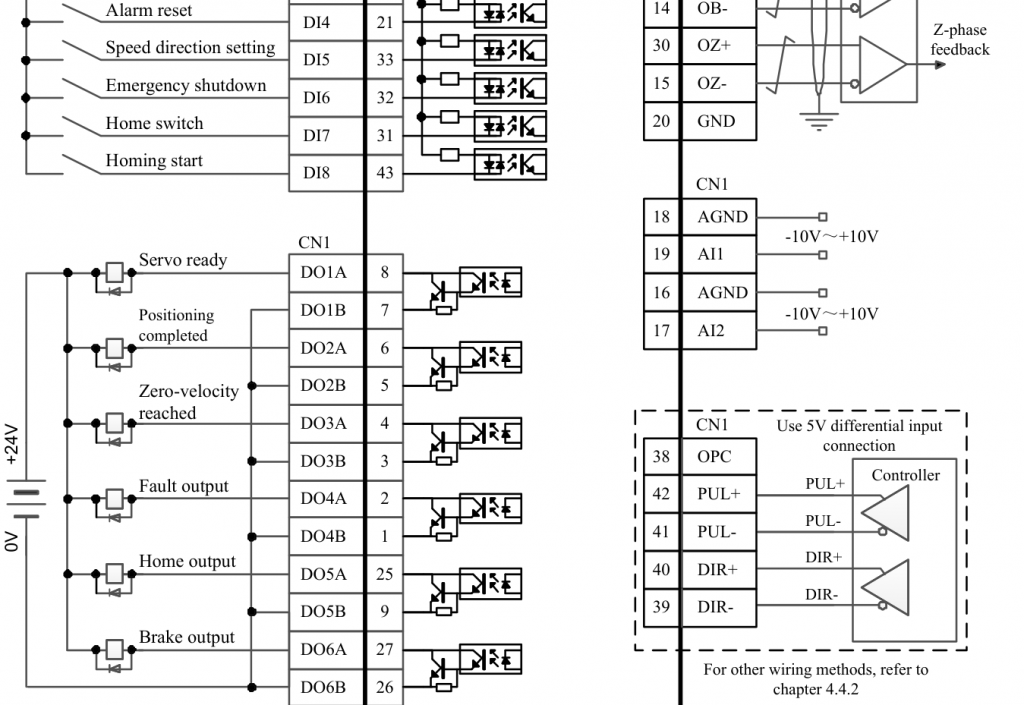
We're getting mixed up. The big industrial drives are absolutely PWM but their command isn't. It's analogue +/-10V. resolved to 12bits and also LPF-ed. Sounds ridiculous when many MCUs output PWM, filter-it and step-it-up to +/-10v, only to be digitized again  But in spite of some of the newer techniques such as pulse/direction, +/-10V analog is used by MCUs that want to handle the PIDs locally (I do). So my objective is only to have something on my desktop that accepts a +/-10V command reference for code development only. I just want to spin these miniature motors-with-encoders to simulate an actual machine. Negligible current and not actually going to be driving a load. I have been running a 1KHz sample-rate for my PID and motion profiler (Settick 1) and still have lots of time outside of the ISR UNLESS I use PWM for the motor command. Writing to the PWM gobbles-up the entire millisecond. Therefore, instead of PWM, I am writing to an SPI-DAC.  This is a typical industrial servo drive. On CN1, A11 and A12 are the analog inputs. One is for those who need the device to be a velocity controller and the other is for those who need the device to be a current (therefore torque) controller. As a velocity controller, the +/- 10V is scaled to the maximum RPM of the motor (velocity gain). As a current controller, the +/- 10V is scaled to the maximum current output (current gain). Lower down, you can see PUL & DIR, pulse and direction. In this mode, the PID is 100% closed inside the drive and the pulses are simply like those of a stepper-motor. They are counted and become a position command for the device. (like Volhout has recently implemented in PIO). I use the current(torque) mode because I want full control  |
||||
| Mixtel90 Guru Joined: 05/10/2019 Location: United KingdomPosts: 6778 |
Right.... So you want +/- 10V input to drive a small motor with just the encoder on it? That really is virtually the sketch that you did at the beginning. :) That's the basic design for adding a power stage to an op amp. You can introduce the usual feedback resistors to make the output stage actually part of the op amp and set the gain of the combination. You can even get power op amps that will do the lot in one package. It will get hot though without PWM. You ned decent heatsinks for analogue. You may even need multiple devices to get the current gain needed in the output stage. Mick Zilog Inside! nascom.info for Nascom & Gemini Preliminary MMBasic docs & my PCB designs |
||||
| PhenixRising Guru Joined: 07/11/2023 Location: United KingdomPosts: 857 |
Actually, that was yesterday  I have been in dialogue with Lichuan in China. I want to use their big stuff but they also have models in the 100W range. Absolutely gorgeous products. I think I'll just go ahead with a few of these. I am so darned geeked with this Pico and especially since Volhout adapted the quadrature decode capability. I should just get the professional rig so that I can make serious YouTube vids. Need to get someone here fired up to tackle a UI and GCode parser/interpreter for the CMM2...We have the horsepower to do a proper job  |
||||
| Mixtel90 Guru Joined: 05/10/2019 Location: United KingdomPosts: 6778 |
Any idea what the stall current of those little motors is? Mick Zilog Inside! nascom.info for Nascom & Gemini Preliminary MMBasic docs & my PCB designs |
||||
| PhenixRising Guru Joined: 07/11/2023 Location: United KingdomPosts: 857 |
My Pittmans? I can have them holding position and when I force the rotor, it's pulling no more than 1.5A to overcome. Holding position with no external disturbance and we're talking milliamps. This is one of the many advantages of servos vs steppers; they only require current when an external force comes into play. Attached the Lichuan manual in case I misunderstood  A5 Series Servo User Manual (detailed version V2.1.3) LOGO 20230711.pdf |
||||
| Mixtel90 Guru Joined: 05/10/2019 Location: United KingdomPosts: 6778 |
I'm even more confused now. That servo controller appears to synthesize 3 phases to power a 3-phase motor. :) Are you trying to *replace* this servo controller & 3-phase motor with a Pico & DC motor arrangement to play with on the bench by any chance? Mick Zilog Inside! nascom.info for Nascom & Gemini Preliminary MMBasic docs & my PCB designs |
||||
| PhenixRising Guru Joined: 07/11/2023 Location: United KingdomPosts: 857 |
No, not related. It's a 3-phase input to an internal DC power-supply. In fact, I have thoughts about that...but for another time. No. I have a lot of coordinated motion code to develop which needs to be on the desktop. My desktop motors are brush-type DC. All that they have in common is that they rotate and have shaft-mounted encoders. The PicoMite has +/-10V motor command output and receives Channel A, Channel B, and Index pulses from the encoder. It has no-idea which motor it is commanding. So, in a nutshell, the Pico is like a microphone that can output +/-10V and I need the power-amp to drive the speakers (motor). Edit: Sorry, I misread the second question  Yes, that's what I'm looking for. Yes, that's what I'm looking for.Edited 2024-09-12 17:12 by PhenixRising |
||||
| Mixtel90 Guru Joined: 05/10/2019 Location: United KingdomPosts: 6778 |
Right, so the available output current from the Pico's amplifier has to be able to handle the stall current of the biggest of your DC test motors, either by literally handling it or by current limiting to protect the output devices or by tripping out. That's why I was asking about the stall current. :) The circuit I posted earlier fits between the Pico (or DAC to be more precise) and the amplifier (unless your DAC already provides a +/- output. I think they are available). A Pico only has a single-ended output relative to GND so that needs to be shifted first. The second stage is what produces the gain. You could get any sensible output up to the limits of your op amp supply rails. Mick Zilog Inside! nascom.info for Nascom & Gemini Preliminary MMBasic docs & my PCB designs |
||||
| PhenixRising Guru Joined: 07/11/2023 Location: United KingdomPosts: 857 |
Stall current yeah/no. The simulator won't be under any load but I need some umph to accelerate to 3000RPM, worst case 0.125seconds. My rig will be something similar to this This demo is not the easiest to follow but it's simulating a flying shear. They are using a separate terminal, linked via Modbus, a motion coordinator and EtherCAT linked servo drives. The terminal and the motion controller, > £2,000 We can do the motion AND better quality HMI (resolution) with a single RP2350  |
||||
| phil99 Guru Joined: 11/02/2018 Location: AustraliaPosts: 2135 |
Even with nothing attached to the motor starting current = stall current for a brief moment. |
||||
| PhenixRising Guru Joined: 07/11/2023 Location: United KingdomPosts: 857 |
As I am simulating a machine, the actual time-to-accelerate is more in the region of 0.2 to 0.4 seconds, relatively gentle. |
||||
| Mixtel90 Guru Joined: 05/10/2019 Location: United KingdomPosts: 6778 |
If the amplifier current limits on startup you don't get very fast acceleration but your output transistors are safe. :) If it trips or shuts down at less than the stall current there's a chance that the motor won't start at all. If you can get things right you can push the transistors out of their safe operating area for a very short time, but you than have to pull them back in before they fail. At 24V across the motor (this is full voltage during a start - plugging as worse - as the armature isn't turning) even the old 2N3055, which is 115W rated, will only supply 4.8A or a touch more to the motor. It will probably need nearly 1A into the base to get that due to the stupidly low current gain at high collector current (which is pretty normal for power transistors). This is with zero load on the motor and is just to overcome the inertia. Mick Zilog Inside! nascom.info for Nascom & Gemini Preliminary MMBasic docs & my PCB designs |
||||
| Volhout Guru Joined: 05/03/2018 Location: NetherlandsPosts: 4222 |
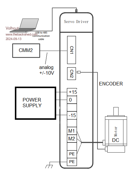
So Phenix, This is what you are trying to accomplish in this phase of the project ??  Volhout P.S. I borowed the picture from the user manual you have posted. Edited 2024-09-13 18:31 by Volhout PicomiteVGA PETSCII ROBOTS |
||||
| Mixtel90 Guru Joined: 05/10/2019 Location: United KingdomPosts: 6778 |
More like !--- 24V motor supply +---------------+ |\! ! ! 0-3 !\ +/-3 !\ +/-10 | \------- ! CMM2 !--------- DAC ------! >---------! >--------| > DC Motor ! ! !/ !/ | / ! ! |/-------- +---------------+ Power Amp ! ! +------------------------------------------------------<----- Encoder I think. :) . Edited 2024-09-13 19:13 by Mixtel90 Mick Zilog Inside! nascom.info for Nascom & Gemini Preliminary MMBasic docs & my PCB designs |
||||
| grumpyoldgeek Newbie Joined: 30/07/2018 Location: United StatesPosts: 31 |
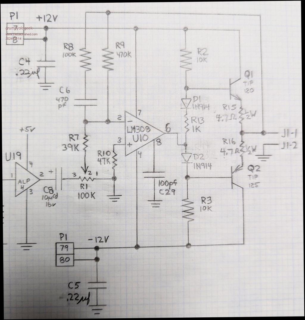
 If you are insistent on going this route, here's a design I did about 25 years ago. It can't drive anything close to 2 amp, but will work and be stable. The transistors are darlingtons and have all the issues of such, and ignore U19, it's a sharp low pass filter for anti-aliasing. I would not suggest this circuit for anything other than experimentation as there are much better ways of doing things. |
||||
| morgs67 Regular Member Joined: 10/07/2019 Location: AustraliaPosts: 75 |
Hi Phenix, I would look at H-Bridge drivers. Advantage being they often have inbuilt limiting and thermal protection. Many are ready to use on small PCBs. There are many (arduino!) control and driver circuits for robots around. Tony |
||||
| PhenixRising Guru Joined: 07/11/2023 Location: United KingdomPosts: 857 |
Bingo!!!  (and I love the drawing) (and I love the drawing)As stated many times, all I care about is rotating my small motor with an analogue command signal where 10V command = 100% current in cw direction and -10V = 100% in ccw direction. The performance/efficiency is irrelevant. H-bridge, No. I have many but I cannot use PWM on the Picomite as my timer ISR is 1ms and writing to the PWM takes at least that. Edited 2024-09-14 16:43 by PhenixRising |
||||
| Mixtel90 Guru Joined: 05/10/2019 Location: United KingdomPosts: 6778 |
To avoid dissipation in the output devices you *have* to use pwm, unfortunately. If that is really impossible then your output devices have to be rated up to the full stall current of the largest motor that you are going to use. You also have to fit heatsinks that will keep those devices cool - or at least stop them melting under starting and plugging conditions. :) You also need some form of protection for the devices against back EMF from the motor. It's quite possible to design an output stage that will do this, but you *have* to know the absolute maximum current that it is going to have to handle before you can start. You can never use a bigger motor than that once it's been built. The above design is a good starting point. It may be necessary to replace Q1 and Q2 with multiple devices (possibly retaining them as drivers), including paralleled outputs, if you need more current. Don't rule out H bridges. They can be analogue or digital depending on how you build them. The cheap little modules are digital but you can do it other ways. The increased torque can be well worth it (if you can spare the heatsink volume!). DC motors are generally not kind to electronics. Mick Zilog Inside! nascom.info for Nascom & Gemini Preliminary MMBasic docs & my PCB designs |
||||
| PhenixRising Guru Joined: 07/11/2023 Location: United KingdomPosts: 857 |
Hi Mick. Just like one would use a circuit simulation app for proving a design, that's what I need but in a small desktop rig. The actual machine is right here next to me but it's a beast and all kinds of costly mischief can happen in the (likely) event of a coding error. The simulator doesn't drive a load. I just need to verify that the motion commands are happening in the correct order without risking damage to the actual machine. Then I simply transfer the analogue command wires and the encoder feedback to the machine's 4.5KW AC Servo and let 'er rip (hopefully not literally).  This small amplifier is not intended for moving anything on an actual machine. For example: I use "electronic gearing" with variable ratio; I disable motor X and turn the rotor by hand. Motor Y is still enabled and now it tracks the motor X that I turn by hand. The ratio can be anything, 1:1, 1:2, 25:1, etc., etc. This is something that has to be developed on a miniature rig.  |
||||
| Mixtel90 Guru Joined: 05/10/2019 Location: United KingdomPosts: 6778 |
Yep, I get that. The problem is that the amplifier has to turn the motors that you *have* got on the miniature rig, isn't it? You want to spin them so the amplifier has to supply that current. They may only be small, but it's still a load for the amplifier and it has to be designed to take it. Without knowing the maximum motor current (even if it's only 100mA) I can't suggest anything. Your other way is not to have a motor of any sort. Simulate one in software on a second computer rigged up with a +/-10V input and an analogue output. That would be an interesting project. Way beyond me though. lol Mick Zilog Inside! nascom.info for Nascom & Gemini Preliminary MMBasic docs & my PCB designs |
||||