|

|
Forum Index : Microcontroller and PC projects : PicoMite: PCF8575 I2C I/O Expander
| Author | Message | ||||
| Volhout Guru Joined: 05/03/2018 Location: NetherlandsPosts: 4222 |
The PCF8574 and similar 8575 are designed for common applications where LED's are between output pin and 3V3 (5V), and pulups are used to detect key switches that connect to ground. When this is your configuration, they work just fine, with the simplest I2C interface possible. If you want more complex IO, then there are the TCA6408 type chips, and probably the microchip that Stan promotes. Volhout PicomiteVGA PETSCII ROBOTS |
||||
| PhenixRising Guru Joined: 07/11/2023 Location: United KingdomPosts: 857 |
Still trying to figure-out what it does  |
||||
| thwill Guru Joined: 16/09/2019 Location: United KingdomPosts: 4036 |
The clue is obviously in the name:  I guess I will get a couple and have a play. I'm still curious about something though, @lizby was suggesting that he was connecting IC pin -> switch -> 3.3V ... what is it that tells us whether that is "safe" for the IC or not, is that not sinking a lot of current through the IC? - remember pretty much everything I know about electronics has been learnt through osmosis on TBS, there is little real understanding - "Dammit Jim I'm a programmer not an electronics-engineer". Best wishes, Tom Edited 2024-09-06 19:47 by thwill Game*Mite, CMM2 Welcome Tape, Creaky old text adventures |
||||
| Volhout Guru Joined: 05/03/2018 Location: NetherlandsPosts: 4222 |
Hi Tom, In case of the PGA2350 I agree. It is much more expensive than a Pico2. But in general it is cheaper to use the next size up microcontroller (if you need more IO pins) than adding additional IO expanders. And typically these additional microcontroller pins are more versatile. The main advantage of "distributed IO" is that you avoid the PCB routing complications (running many traces from fine pitch chips like BGA's). Volhout Edited 2024-09-06 21:31 by Volhout PicomiteVGA PETSCII ROBOTS |
||||
| lizby Guru Joined: 17/05/2016 Location: United StatesPosts: 3150 |
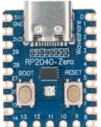
This on "wiring-pcf8575-as-input" has good information, including: "This part is not ideal for being used for many buttons because of this. Each button you press will have ~100mA of current flowing to ground." They recommend the TCA9555, but the modules on aliexpress are fairly expensive, and have 24 pins. With that in mind, I'd be more inclined to use an RP2040-Zero:  ~ Edited 2024-09-06 22:14 by lizby PicoMite, Armmite F4, SensorKits, MMBasic Hardware, Games, etc. on fruitoftheshed |
||||
| PhenixRising Guru Joined: 07/11/2023 Location: United KingdomPosts: 857 |
Also the added on-board intelligence and more watchdogs. When my main controller is waiting for a "Start" signal, the slave takes care of determining the validity: -A normally-closed contact must open -A normally-open contact must close -That state must persist for tens of milliseconds. The main controller receives a true/false.  |
||||
| phil99 Guru Joined: 11/02/2018 Location: AustraliaPosts: 2135 |
As it is able to drive LEDs directly (no series resistor) the outputs appear to have current limiting. |
||||
| Volhout Guru Joined: 05/03/2018 Location: NetherlandsPosts: 4222 |
Hi lizby, I am sure that 100mA only applies when you change the pin output state while the button is pressed. The idea however is that for input pins you ALWAYS send a logic high to the associated output pin register for any pin that is targetted input, even if you toggle other pins that are intended as output pins. In that case the 100mA do not apply. Volhout Edited 2024-09-06 23:11 by Volhout PicomiteVGA PETSCII ROBOTS |
||||