
|
|
Forum Index : Microcontroller and PC projects : Pico LC meter
| Author | Message | ||||
| phil99 Guru Joined: 11/02/2018 Location: AustraliaPosts: 3294 |
Another way to test the oscillator:- Exit program then copy and paste this to the terminal clear :setpin gp0, off : setpin gp0, fin : pause 2000 :? pin(gp0);" Hz" If it isn't running the result will be 0Hz Edit. First you may need to make GP0 a count pin. Eg OPTION COUNT GP0,GP1,GP6,GP7 The DC voltages on the LM311 pins 2,3 and 7 should all be the same and close to 2.5V. Edited 2024-07-22 17:45 by phil99 |
||||
| Volhout Guru Joined: 05/03/2018 Location: NetherlandsPosts: 5945 |
Joachim, phill, With a digital voltmeter, you can safely probe pin 3 of the LM311, and see if it has 2V - 3V on it. When not, the LM311 is not oscillating. I do not suggest to probe pin 2. It is possible that the oscillator stops with a multimeter probe attached. With an analog meter, probing the LM311 output is safest. And yes, it should be between 2V and 3V. When there is no oscillation, check - polarity of the electrolitic caps (10uF ones) - Is the LM311 a real LM311, or are you using an LM393/339. The 393 is too slow. Note: when in "inductor measure" mode, and open test leads, the oscillator will not run. This is handled by the software, to detect it does not run. But you will not see a signal at the LM311 output. So do above in capacitor test mode. Volhout Edited 2024-07-22 19:36 by Volhout PicomiteVGA PETSCII ROBOTS |
||||
| v.lenzer Senior Member Joined: 04/05/2024 Location: GermanyPosts: 117 |
Hi Volhout! If the 6K8 resistor is connected to pin 7 of the LM311, I measure 2.57 V. If I disconnect the resistor, I measure 4.7 V. There is a stable hi level on the scope - no PWM. On Pin 3 are also 4.7V. So something is wrong with the oscillator. I have to check all the connections. What does the position of SW2 mean in your circuit diagram? According to the label it would be "induction measurement". Am I right? I'll get that sorted. Now I know what to look out for. Thank you for your tip. By the way, question: I'm interested in your component tester. Would it be possible to use it with an RP2040-Zero and an ILI9341 via SPI? Edited 2024-07-23 04:28 by v.lenzer Best wishes! Joachim |
||||
| Volhout Guru Joined: 05/03/2018 Location: NetherlandsPosts: 5945 |
Sw2 selects between capacitor and inductor test. Shown position in the circuit diagram is for testing inductors. When adding 6.8k to the lm311 output has that much impact, the 1k resistor to 5v is wrong value, or defect. Volhout PicomiteVGA PETSCII ROBOTS |
||||
| Rickard5 Guru Joined: 31/03/2022 Location: United StatesPosts: 463 |
WOW just WOW, I'm gonna build one, I wish there was a PCB Gerber for it :) I may be Vulgar, but , while I'm poor, I'm Industrious, Honest, and trustworthy! I Know my Place |
||||
| Mixtel90 Guru Joined: 05/10/2019 Location: United KingdomPosts: 8913 |
Well, you have the schematic and an approximate layout. It would be a nice little project for you to play with on SL6. The library includes the DIL packages and I can send you macros for the RP2040-Zero and the CMM2 pcb and case, probably others too. You'd still have to create some macros, but it's very easy once you find mechanical drawings for components and it's something you'd need to learn how to do anyway. Go on, have a go. It doesn't matter if you make a complete mess of it, just delete what went wrong or even start again. Edited 2024-07-23 16:22 by Mixtel90 Mick Zilog Inside! nascom.info for Nascom & Gemini Preliminary MMBasic docs & my PCB designs |
||||
| v.lenzer Senior Member Joined: 04/05/2024 Location: GermanyPosts: 117 |
The LC meter seems to be working! I had connected the 1k resistor incorrectly. There was also a short circuit on the board. I use a 0.96" OLED, which is why I changed the value output a little. However, it seems to me that the measured values are still not correct. With an 816 pF 1% capacitor, I get the value 1661.64 pF. With a new measurement with the same capacitor, it was 832 pF. That would be OK, because it is still within the tolerance range. With the coil, I get the value 132 or 64 uH. The coil has the value 82 uH. But I don't know the tolerance (yet). I have to read the whole post again so that I understand how the calibration and switching works. But for now, I'm happy that the de vice works at all. I can also now start building the housing. 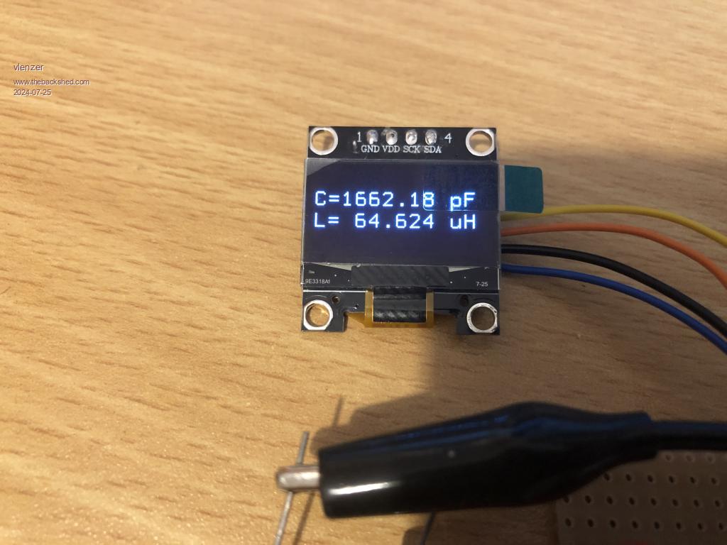 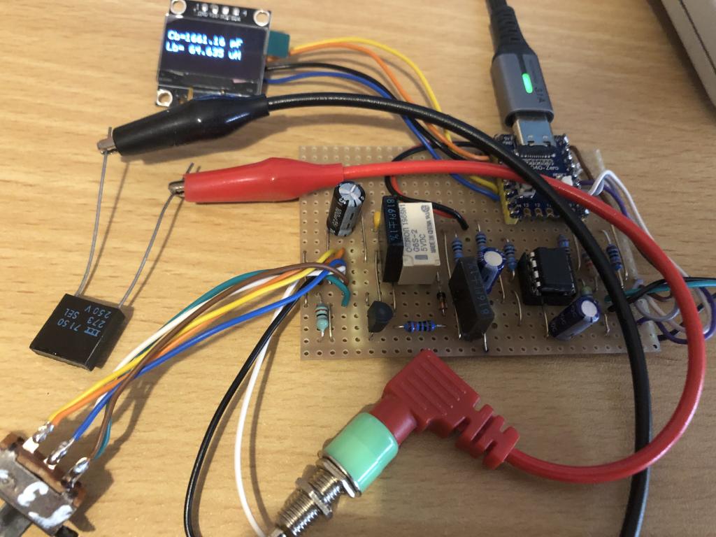 Edited 2024-07-25 03:28 by v.lenzer Best wishes! Joachim |
||||
| Volhout Guru Joined: 05/03/2018 Location: NetherlandsPosts: 5945 |
Good work !! You have solved the issue. OK, let me explain how to operate the device. 1/ You select capacitor test 2/ You press ZERO for 1-2 seconds, then release the button. 3/ The display should read 0.0pF now. Now your instrument is zero'ed, and good to measure inductors and capacitors. When you use wires, test leads or some kind of adapter. Hold the leads as if you are to measure the part you want to measure When you want to measure a capacitor, select capacitor, don't let the test probe tips touch each other, and press ZERO. Now you are good to measure capacitors with these long test leads. When you want to measure an inductor, select inductor, and short circuit the test pins (an infinitely small inductor value), and press ZERO. Now you have compensated the test leads inductance, and you can measure the inductor you want with the test lead probe tips. With small capacitors (pF) or inductors (few uH) it is important to keep the test leads as much as possible unaltered between zero and measurement. I notice in the photo that you are using a normal mechanical relay, not a reed relay. Normal relays are slower in switching (*), and (unless you have gold plated contacts) will not work reliable over time. Mechanical relay contact require a minimum current to switch reliable. And in this application the current is too low. Only reed relays are proven to work in this application. But you may be lucky. If your relay has gold plated contacts it will work quite well. Have fun with this tester. It serves me well. So it will fo ryou. Volhout (*)= in lines 58 and 64 you can change the PAUSE 10 to PAUSE 20, that should be okay for a mechanical relay this small size. (**) when you see L and C both in the display, you are in ZERO mode, and you see the debug message of the compensation. If you ZERO with 816pF attached, it will compensate for the total capacitance of 816+816=1636pF. Normally you ZERO with open leads. Edited 2024-07-25 05:36 by Volhout PicomiteVGA PETSCII ROBOTS |
||||
| v.lenzer Senior Member Joined: 04/05/2024 Location: GermanyPosts: 117 |
Thank you very much for your explanations! My mistake was also that I had a capacitor on the test leads when I switched to Calibrate. That can't work. Now I know. I'm going to change the relay. I still have reed relays somewhere in the depths of my toolbox. Best wishes! Joachim |
||||
| v.lenzer Senior Member Joined: 04/05/2024 Location: GermanyPosts: 117 |
Hello Volhout! I need your help again, please. I have now installed a reed relay and printed a housing. 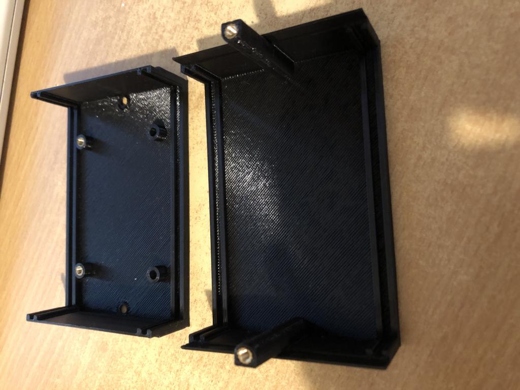 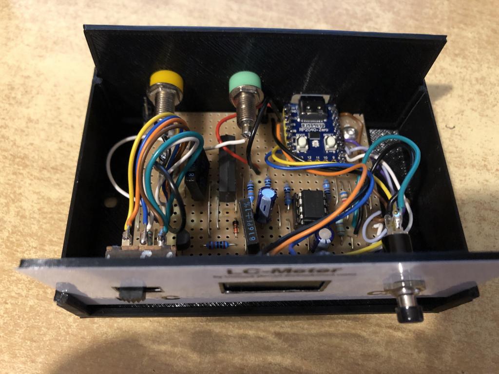 But the measurement result has not changed. I cannot get out of the test loop. I did the following: The test probes were disconnected, no capacitor connected. The slide switch was set to "C" (=capacitance measurement). After switching on, this display appears. 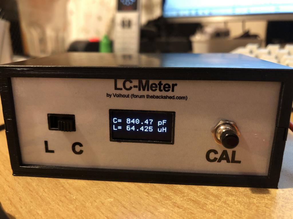 Then I pressed CAL. 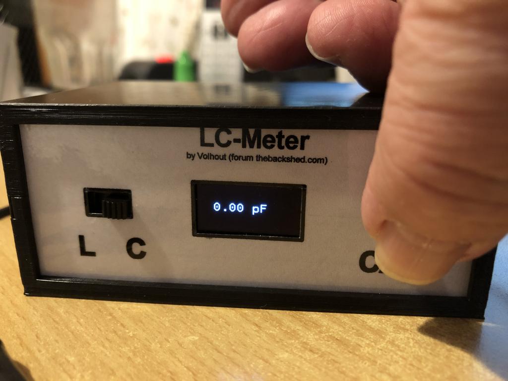 Then I clamped an 816 pF capacitor between the test terminals. And this is what is displayed. 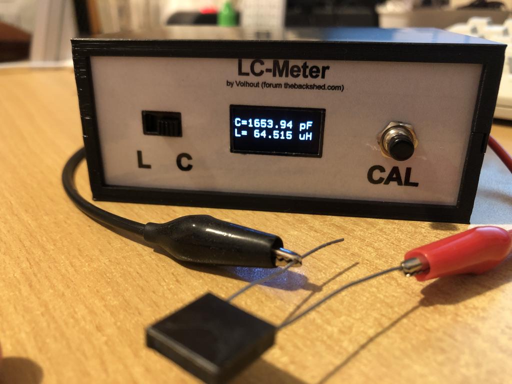 Then I removed the capacitor, put the test probes together and switched to "L" (inductance measurement). This display appears. 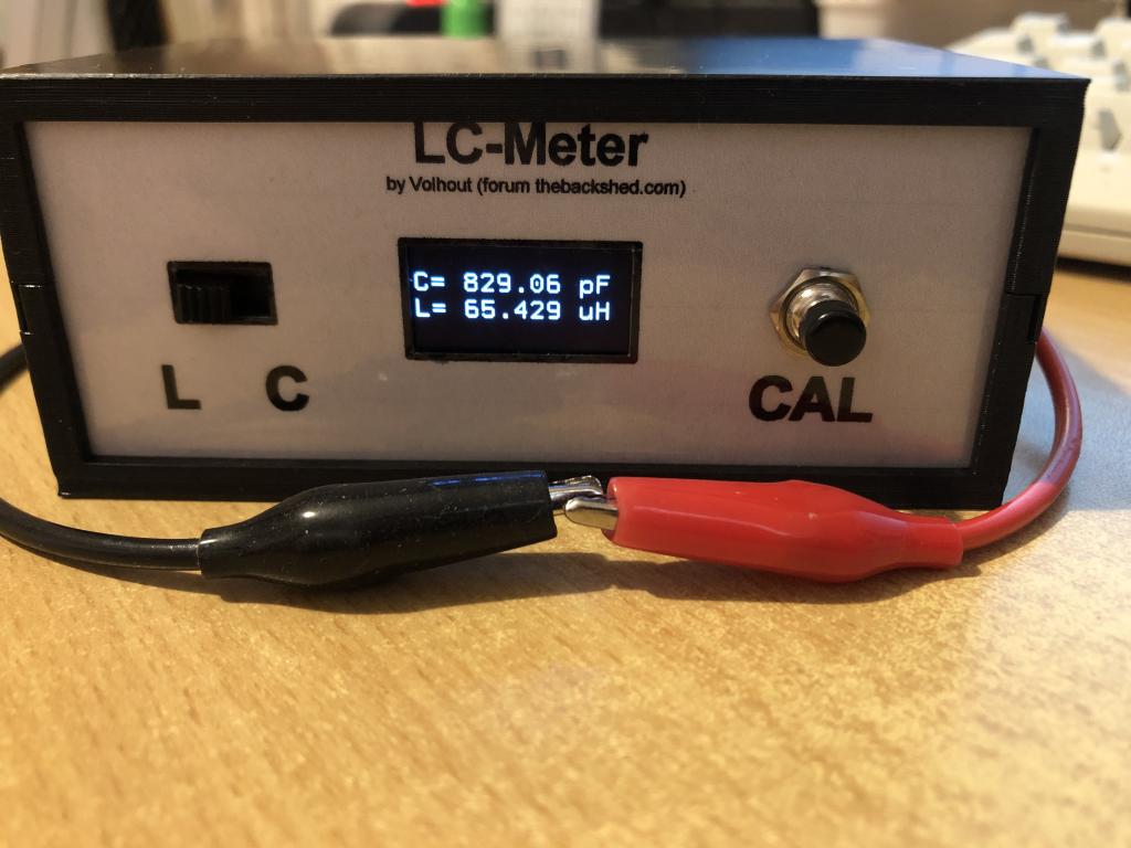 Then I pressed "CAL" and this display appears. 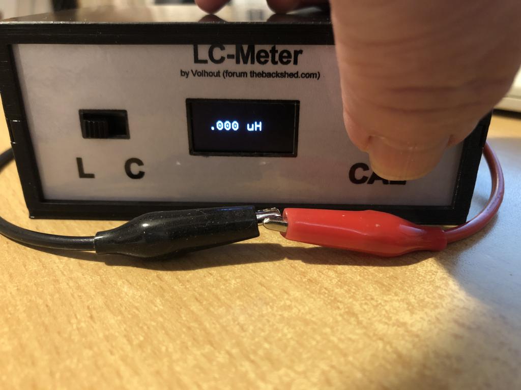 Now I clamped an 82 uH coil between the probes and this display appears. 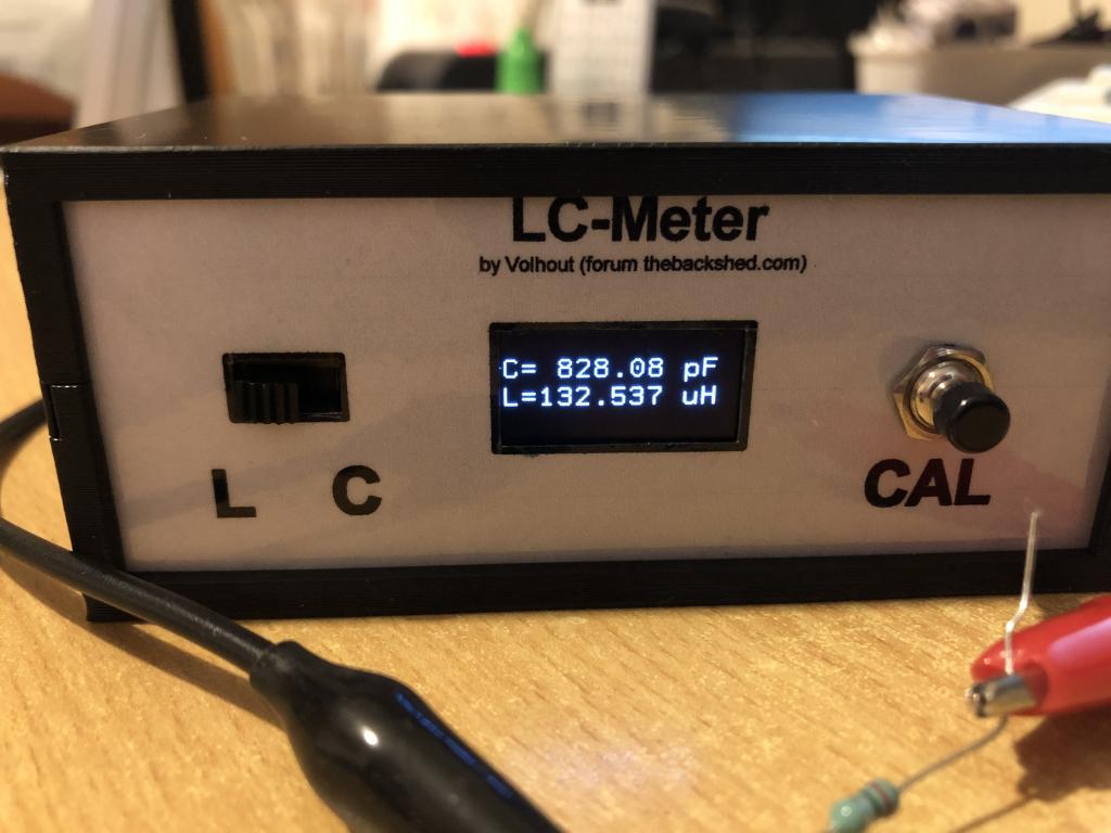 I have checked the circuit for hours and cannot find any errors. The reed relay switches. You can hear it. It is a normally closed switch. Can you please give me a tip as to where a measuring point is or in which area I could look. Edited 2024-07-31 02:46 by v.lenzer Best wishes! Joachim |
||||
| Volhout Guru Joined: 05/03/2018 Location: NetherlandsPosts: 5945 |
You CAL button works reverse. I used a NC switch, you have NO button. Simplest fix is to change the line If oldkey=1 Then in If oldkey=0 Then Volhout B.t.w: very nice and sharp pictures . Edited 2024-07-31 06:48 by Volhout PicomiteVGA PETSCII ROBOTS |
||||
| Volhout Guru Joined: 05/03/2018 Location: NetherlandsPosts: 5945 |
Joachim, Thank you very much for building this, and mentioning my name on the front panel. I feel very much honoured.!! This is a great compliment to me. I hope it serves you well, and you will have many good memories of the build and construction. Volhout PicomiteVGA PETSCII ROBOTS |
||||
| v.lenzer Senior Member Joined: 04/05/2024 Location: GermanyPosts: 117 |
Hello Volhout! After studying the test loop, I had already changed the button query to "If oldkey=0 Then" and that got me out of the loop. But the measured values were completely wrong. So I thought that couldn't be it. Now I've installed an opener and the result is again that the values are wrong. An 816 pF capacitor is measured at 9.8 pF and a 100 nF at 4.10 nF. An 82 uH coil is measured at 7.1 uH. There's still a worm in my circuit somewhere. This is my breadboard setup. It looks a bit strange in the area of the relay. But that's because the relays have been replaced. 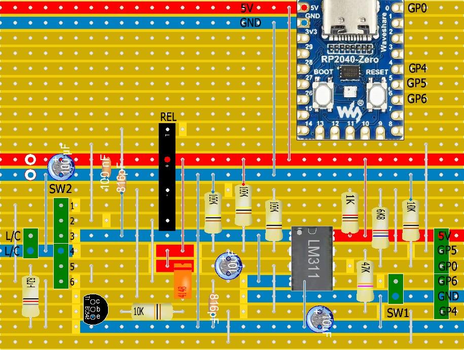 Best wishes! Joachim |
||||
| phil99 Guru Joined: 11/02/2018 Location: AustraliaPosts: 3294 |
Drew the circuit from the stripboard layout above and it matches Volhout,s circuit. The only thing not clear is the connections to SW2. A slightly simplified layout might be:- 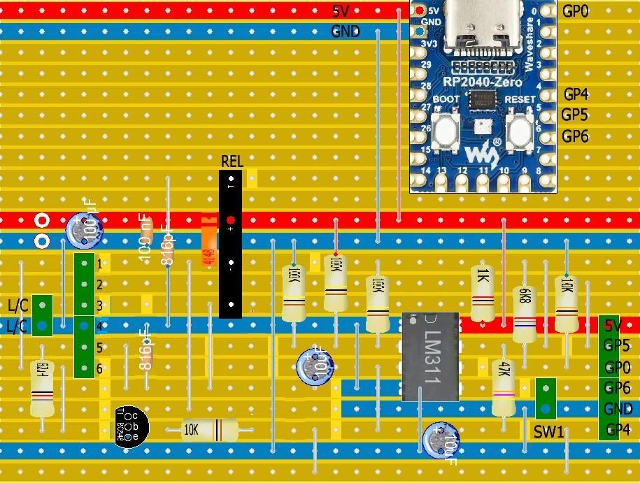 |
||||
| v.lenzer Senior Member Joined: 04/05/2024 Location: GermanyPosts: 117 |
Thanks for checking the breadboard layout and simplifying it. The assembly looked like this before. 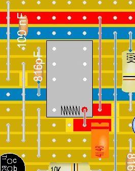 Hence the position of the freewheeling diode. Here is the assignment of SW2. The red numbers correspond to the numbers on the breadboard layout. 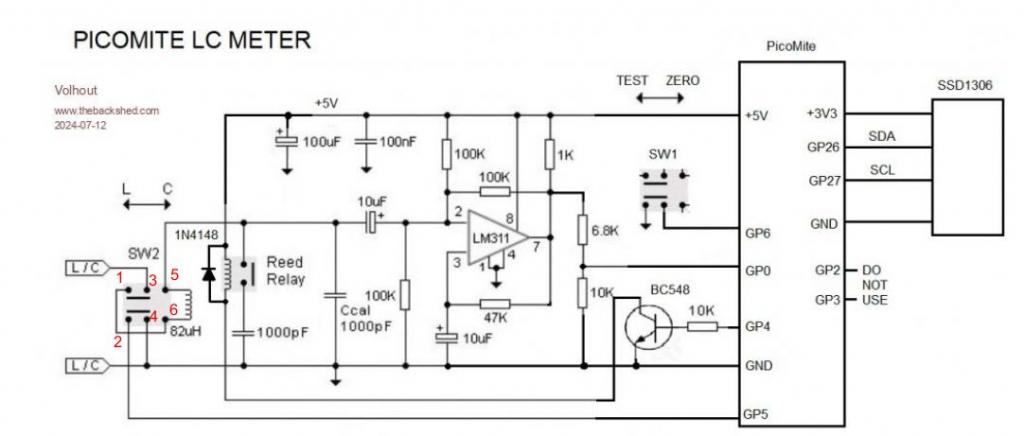 How did you change the graphics? Perfect! Edited 2024-07-31 16:35 by v.lenzer Best wishes! Joachim |
||||
| phil99 Guru Joined: 11/02/2018 Location: AustraliaPosts: 3294 |
MS Paint, copy & paste. |
||||
| Volhout Guru Joined: 05/03/2018 Location: NetherlandsPosts: 5945 |
Hi Joachim, Sorry for the late reply. Looking at the pictures you posted some posts back, the LC meter works fine for small inductors and capacitors, only the CAL button was revered. Now you mention the measured values are completely wrong. Is there a break in the wiring somewhere ? Did you change more than the single line in the code ? I am not sure what causes this. Can you try the original software again (just use the original version I published) with the wrong CAL button. Do you see the same values as before ? Or is the hardware defective now? Volhout PicomiteVGA PETSCII ROBOTS |
||||
| Mixtel90 Guru Joined: 05/10/2019 Location: United KingdomPosts: 8913 |
Would anyone like me to do a PCB for this? It looks like it would fit the little Multicomp MCRM2015S case (like a baby CMM2). Peter used it recently. Mick Zilog Inside! nascom.info for Nascom & Gemini Preliminary MMBasic docs & my PCB designs |
||||
| Volhout Guru Joined: 05/03/2018 Location: NetherlandsPosts: 5945 |
Hi Mick, If there is interest from others I would definitely offer my help for the people that build one. But I have mine on veroboard, and it works nice. This instrument will last the rest of my active hobby life. I am not building another one unless it would help someone else. But there are some on this forum that might beinterested in one, and maybe Geoff can publish it in Silicon Chip magazine. Elektor magazine is very much ESP32 focussed, and may not be interested in any mite. Volhout Edited 2024-08-01 16:21 by Volhout PicomiteVGA PETSCII ROBOTS |
||||
| pwillard Guru Joined: 07/06/2022 Location: United StatesPosts: 341 |
I made one back in 2013 based on the original design with Arduino. Here's mine. 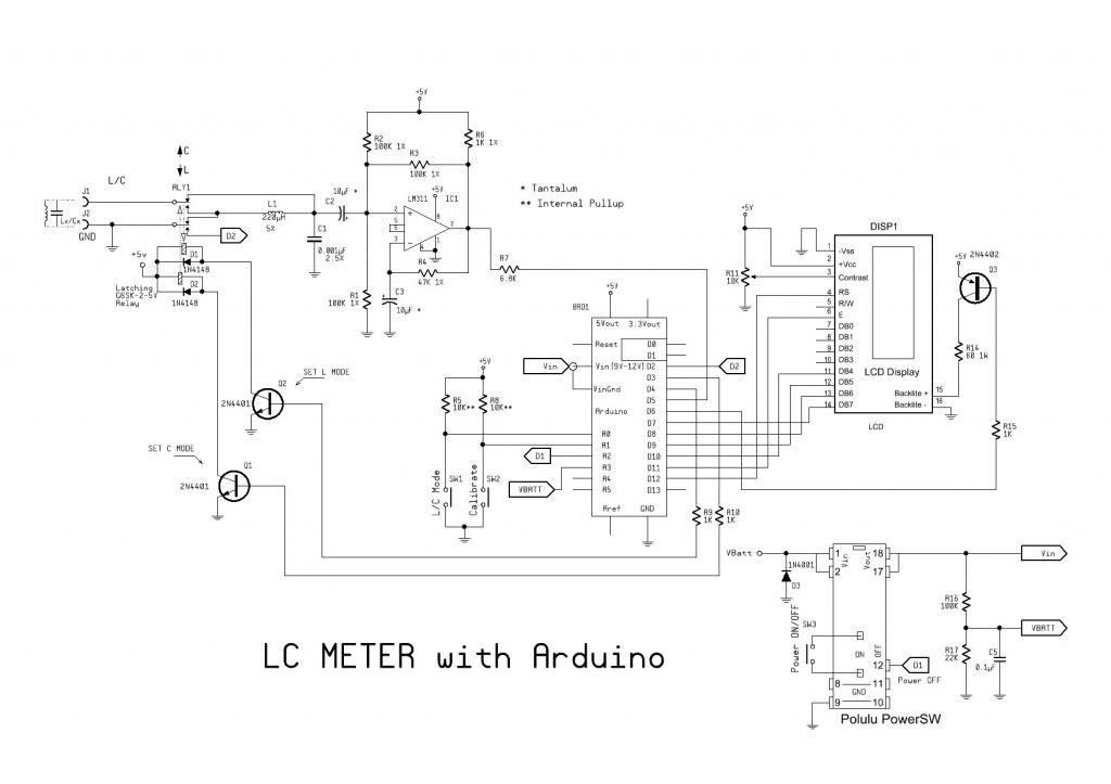 pwillard.com Edited 2024-08-01 22:00 by pwillard |
||||
| The Back Shed's forum code is written, and hosted, in Australia. | © JAQ Software 2026 |
