|

|
Forum Index : Microcontroller and PC projects : $5AU Raspberry Pi Pico
| Author | Message | ||||
| Volhout Guru Joined: 05/03/2018 Location: NetherlandsPosts: 4223 |
I think that will not be easy. It should be easy enough to extract the PIO code from the program, and I think it is do-able to understand how to control the PIO engine (re-program the PIO when trigger settings change) with a little study of the code. Reading the data from the packed array is also pretty straightforward. But the display code is written around 640x480 resolution (mode 1), and uses tiles for highlighting and color. Going back to 320x240 LCD resolution may not give you a good viewing resolution for the traces and would also require you a complete re-write of the display routines. Maybe a 480x320 LCD could give more resolution, but it would update realitively slow, since the FRAMEBUFFER is 320x240 so it can't be used. But.. there may be a solution. If you search a bit on the web, you occasionally come accross a cheap 5-7 inch LCD monitor that has 640x480 resolution, and features a VGA connector (besides composite). These are sometimes marketted as rear view camera monitor. I bought one of those, for slightly over the price of the bare LCD (25-30 dollar) and it is giving a good picture. Such as this (watch for the "sale") The monitor I have Then it is 4 resistors on your Pico-ZERO, and you are done. Volhout Edited 2024-07-04 16:44 by Volhout PicomiteVGA PETSCII ROBOTS |
||||
| phil99 Guru Joined: 11/02/2018 Location: AustraliaPosts: 2135 |
Depending on the overall pulse rate the PULSIN Function in a loop may do what you want. It has a resolution of +/- 0.5µS. The CPU speed determines the maximum speed of the loop and thus the maximum pulse rate. At 200MHz I have no trouble reading 25µS pulses 50µS apart. At 378MHz it could do a lot better. |
||||
| Volhout Guru Joined: 05/03/2018 Location: NetherlandsPosts: 4223 |
In case you just want to measure 1 input pin, you do not need the logic analyzer or diffucult code. This is for GP0 measurement of a period (mark+space). 'Period measurement using PIO Option default integer 'pio program measure pause and pulse time from GP0 in us and push both to FIFO '0 E020 'set X=0 '1 A029 'X -> fffffff '2 00C4 'jmp (pin=1) to loop2 '3 0042 'count loop1 '4 0045 'count loop2 '5 00C4 'jmp (pin=1) in loop2 '6 A0C9 'mov -X to ISR '7 8000 'push noblock '8 0000 'jmp 0 (rest is filled with 0 = jmp->0) Dim a%(7)=(&h004200C4A029E020,&h8000A0C900C40045,0,0,0,0,0,0) f=2e6 '2MHz 'configure pio1 e=Pio(execctrl gp0,0,&h1f) 'use gp0 for PIN s=Peek(word &h503000d0) 'use old value p=0 'no GPxx pins for PIO 'program pio1 and start PIO program 1,a%() PIO init machine 1,0,f,p,e,s PIO start 1,0 frequency: 'measure time and convert to frequency Do ' cnt=Peek(word &h50300020) 'read fifo pio 1 seq 0 pio read 1,0,1,cnt 'read fifo pio 1 seq 0 period = cnt+3 'period is 2x pulse or pause time Print period;" us "; 1e6/period;" Hz " Pause 100 Loop While Inkey$="" Return This essentially measures the pulse width, but converts it to frequency. Regards, Volhout Edited 2024-07-04 18:00 by Volhout PicomiteVGA PETSCII ROBOTS |
||||
| v.lenzer Regular Member Joined: 04/05/2024 Location: GermanyPosts: 49 |
I have been programming in machine language for many decades on my first computer: a ZX81. Some of you probably know the tiny thing. Of course, I have also tried other processors and controllers. My ZX81 has several Z80 PIOs. To control the output of these PIOs, I wrote a data logger with the ZERO and I always read in a byte that is poked into the RAM. Then I can look at the result at my leisure and browse through it. You can see the result here: Video Logger The quality of the video is not good because it is difficult to film displays. In the meantime, I have expanded the program and I can display the addresses of connected I2C devices. I have also now distributed the output of the logger result over 8 lines. I have created a font for the output of the Hi and Lo. In fact, I only enter "00110010" via "TEXT...". What you are offering me is sensational. I will read up on PIO programming. As far as I know, there is a manual for it. It all looks like MC programming. Considering that I have only known the ZERO for a few weeks, I have already been able to learn a lot from you. Edited 2024-07-04 20:03 by v.lenzer Best wishes! Joachim |
||||
| Volhout Guru Joined: 05/03/2018 Location: NetherlandsPosts: 4223 |
Hi Joachim, If you want to learn the PIO state machines in the RP2040, you can (try to) read through this: PIO explained Also appendix F of the PicoMite user manual discusses PIO. Note that during the time of the training course PIO EXPLAINED hinted above, changes where made in MMBasic to fix bugs and add features. Not all examples may work 1:1 as in the thread. I will help you if you run into problems. But regardless, the training (and discussions in it) are worth reading, and trying. As a reference, always use the RP2040 datasheet, chapter 3. RP2040 Regards, Volhout P.S. Nice logger. And menu structure. P.P.S. First I was a bit confused about ZX81 and PIO, but then I realized there was a chip in the Z80 family that was called Z80 PIO (and Z80 CTC etc..). . Edited 2024-07-04 20:23 by Volhout PicomiteVGA PETSCII ROBOTS |
||||
| lizby Guru Joined: 17/05/2016 Location: United StatesPosts: 3150 |
Ah, he reveals his (relative) youth. ;-} We hardy stock old pioneers of the microprocessor revolution know all about the Z80 peripherals. I wire-wrapped many a one (that was after walking to and from school in the blizzard uphill both ways (actually, I was long out of school)). ~ Edited 2024-07-04 21:36 by lizby PicoMite, Armmite F4, SensorKits, MMBasic Hardware, Games, etc. on fruitoftheshed |
||||
| Mixtel90 Guru Joined: 05/10/2019 Location: United KingdomPosts: 6783 |
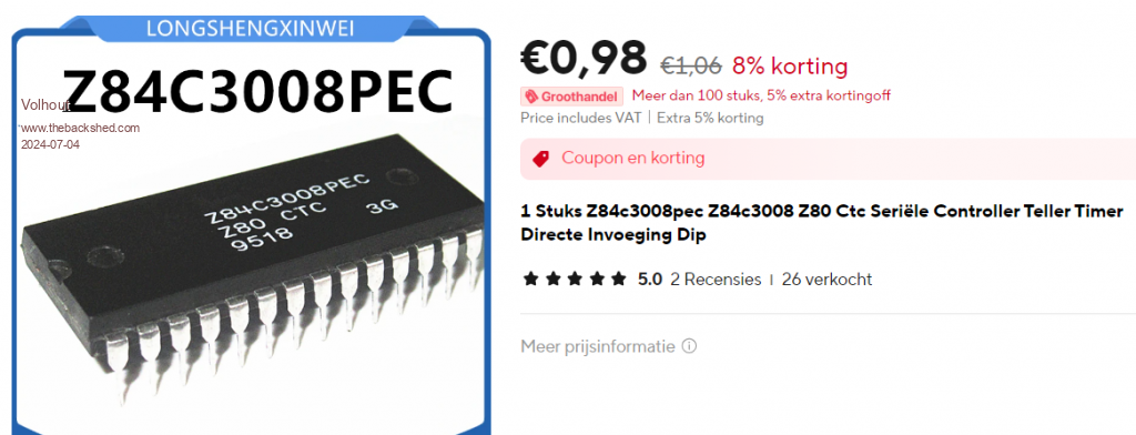
The Z80 CTC was a pretty expensive chip IIRC. I had a Z80 PIO on my Nascom-1 but they used a more conventional UART than the Z80 SIO. Mick Zilog Inside! nascom.info for Nascom & Gemini Preliminary MMBasic docs & my PCB designs |
||||
| Volhout Guru Joined: 05/03/2018 Location: NetherlandsPosts: 4223 |
Cheap as dirt... Build a new NASCOM...   Edited 2024-07-04 23:02 by Volhout PicomiteVGA PETSCII ROBOTS |
||||
| Mixtel90 Guru Joined: 05/10/2019 Location: United KingdomPosts: 6783 |
Amazing what the passage of time can achieve, isn't it? lol At that time (1978 IIRC) the 2MHz Z80 alone cost about £80 if you tried to buy one. The Nascom-1 kit was, IIRC, £198 for a PCB, some bags of components, a keyboard (with Licon switches) and two manuals. You had to buy the PSU and a TV separately. You needed a cassette recorder too if you wanted to save anything (no leads included). Your money bought you a machine code monitor (no BASIC) and a bit less than 1kB of RAM. The screen memory took the other 1kB that was on the board. It was the only computer (that could work with a keyboard and monitor as supplied) available in the UK for less than £1000. Mick Zilog Inside! nascom.info for Nascom & Gemini Preliminary MMBasic docs & my PCB designs |
||||
| Volhout Guru Joined: 05/03/2018 Location: NetherlandsPosts: 4223 |
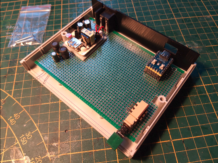
Thank you Mick, for introducing me to the ZERO. Today I also stumbled upon a few G738 housings for near nothing. I am finally going to put some of my test equipment in boxes now, with the ZERO's. Too much proto circuits on breadboards, that never where finished. Below the basis for the capacitance/inductance meter. The power supply is a phone charger (4 euro, taken out of the plastic) with additional noise filter (pi filter). This is essentially the basis for a range of test equipment. I also have the frequency counter on a breadboard. That should go in a box too. And in the back of my head is also a power supply. B.T.W. All these will get remote control through RS485.  Volhout Edited 2024-07-05 05:09 by Volhout PicomiteVGA PETSCII ROBOTS |
||||
| Martin H. Guru Joined: 04/06/2022 Location: GermanyPosts: 1113 |
The thing arrived at the weekend, so far what I have tested has worked so far. 'no comment |
||||
| Mixtel90 Guru Joined: 05/10/2019 Location: United KingdomPosts: 6783 |
Excellent news! :) Mick Zilog Inside! nascom.info for Nascom & Gemini Preliminary MMBasic docs & my PCB designs |
||||