
|
|
Forum Index : Electronics : Mab1's wiseguy inverter build - transformer options
| Author | Message | ||||
| KeepIS Guru Joined: 13/10/2014 Location: AustraliaPosts: 2177 |
Well this is interesting: The toriods were tested one at a time when verifying each individual output. The three stack obviously had a different primary winding. I was simply looking at the power on an AC mains meter, like the one on the front of the Inverter. I was only checking for a steep transition in power and looking for an indication of the beginning of saturation and simply noted the power for each voltage. Each winding is 93vac on the series three stack, and the first winding on each core. I looked at power at a nominal 230V output when wound for the same AC input design voltages I would use for my inverter, again using a variac. When built, I then looked at the DC input power to the inverter at idle for the three stacked toriods, and it was close to the same power as a single smaller aerosharp in the inverter, and the same as, and in many cases way below other single toriod inverters, both toriods were wound to produce the same AC output with same input as above, and the power just happens to be within a few watts with my crude testing with a variac for both. I cannot tell if my inverter is running three toriods or a single toriod by looking at inverter Idle power. Hopefully you can document the correct method that we should all employ, so ongoing individual tests will all compare like for like, it's all a learning curve, and that would also be valuable for future reference. Perhaps a procedure for both inverter idle power and initial variac testing comparisons would be of great help.  . NANO:Inverter V 8.2ks - Linux AvrDude GUI script V4.1 |
||||
| mab1 Senior Member Joined: 10/02/2015 Location: United KingdomPosts: 282 |
Slow progress: i forgot how hard the green potting in the transformer centre on the 1st santerno was - I'd swear it's harder than concrete 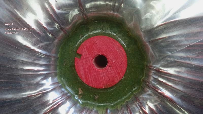 But once I'd chiseled a bit of the splayed edges out i was able to drive it out with a hammer, although i will need to grind a new tip on the chisel. So unwound the mylar tape, the outer 230v winding, and about 6 more layers of mylar tape, and now have a matched pair, each with 155 turns. 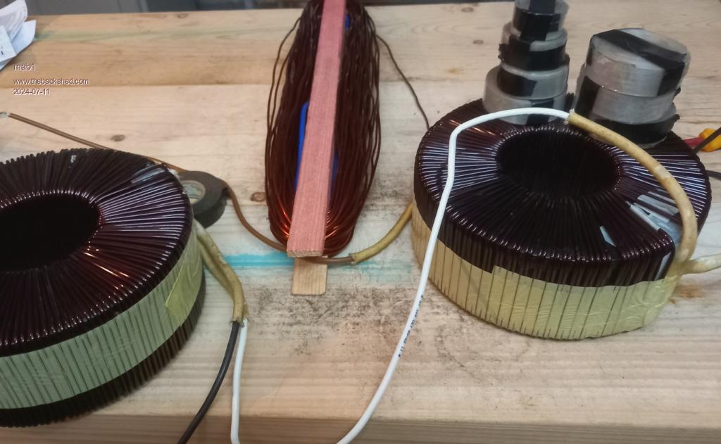 So after a pause to recover from unwinding, i can start unwinding for 121 turns each, which would leave each core with 1 1/2 layers of winding and the wires coming out on opposite sides Although, there is a little (purist) voice suggesting i could unwind them completely, stick them together and wind just 61 turns back on - probably depends on how masochistic I'm feeling  |
||||
| Murphy's friend Guru Joined: 04/10/2019 Location: AustraliaPosts: 678 |
Aw, go on, haver fun and unwind it completely  . .Its always good to know what the core looks like and you can get its area precisely for the 1 tesla flux calculation. Should you choose to follow my advice  then to keep the cores lined up precisely, use a (split and bent to size) waxed PVC tube section while they are epoxied together. then to keep the cores lined up precisely, use a (split and bent to size) waxed PVC tube section while they are epoxied together.To get nice rounded edges to be kinder to your wire (and hands pulling it tight) I suggest you make up 2 plywood disks to epoxy onto each side. These are much easier to round the edges of, with no loss to core area. There is plenty of info about winding stacked cores on this forum. |
||||
| tinyt Guru Joined: 12/11/2017 Location: United StatesPosts: 559 |
Just a suggestion, embed a thermistor in the winding. It is good to know the internal temperature of the toroid during operation. |
||||
| mab1 Senior Member Joined: 10/02/2015 Location: United KingdomPosts: 282 |
 I'm still procrastinating as to which way to go. I am leaning towards unwinding completely, but if i go that way i must un-kink the wire to rewind. I'm still procrastinating as to which way to go. I am leaning towards unwinding completely, but if i go that way i must un-kink the wire to rewind.I've unwound this one to 121 turns: 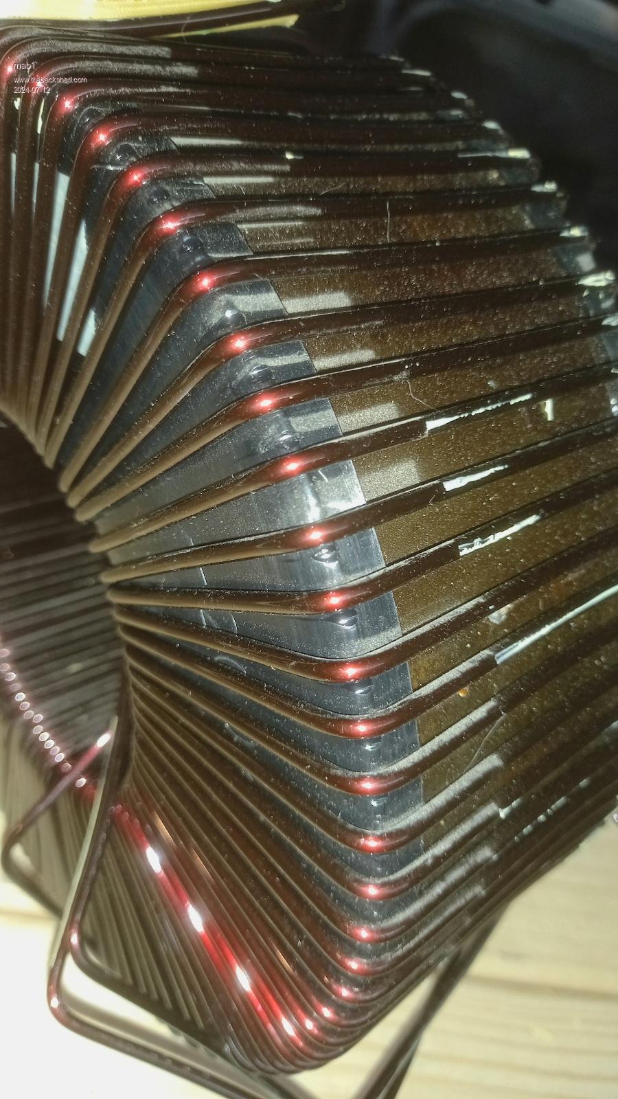 I've been looking at old posts to see what others have done and there seems to be a method of pulling through three bearings to flex and straighten the wire (oztules?), but that presumably work hardens the wire, and it looked to be thinner wire than these (the 230v winding is approx 2.5mm diameter; the 180v 2.8mm diameter). I managed to mostly dekink the 2.5mm with my thumbs but the 2.8mm is kinked tighter and doesn't unkink so well so I'm wondering how much of an issue slightly kinky wire is - with just 61 turns it doesn't have to pack tightly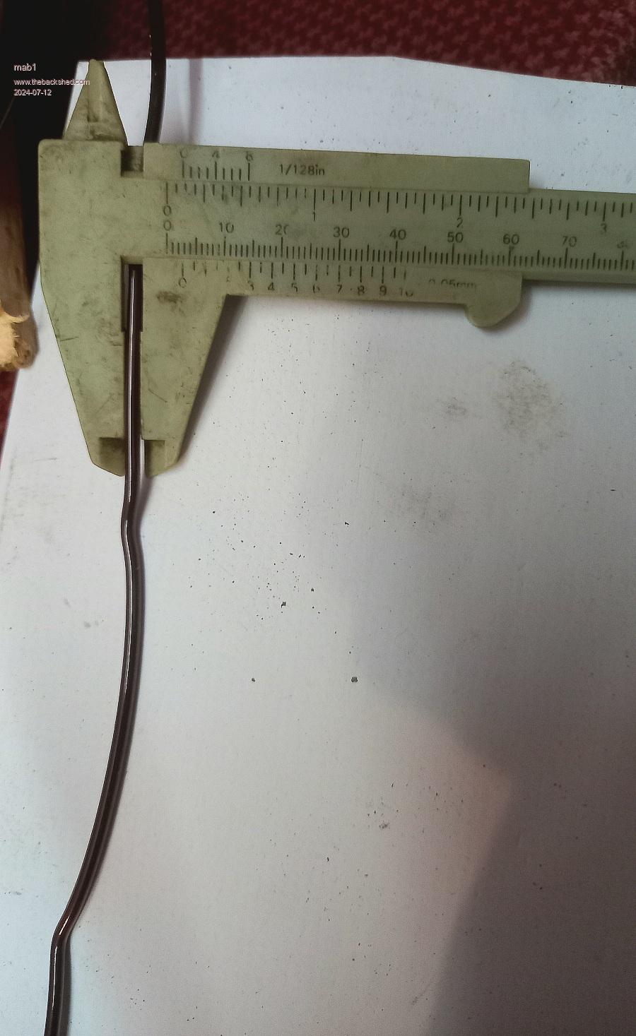 These cores actually have black plastic 'end caps' (see pic above), approx 1.5mm thick so i was thinking they might be re-used for corner protection? I certainly could add a temp probe - although with a double stack i shouldn't ever get it hot. Edit: actually i can still remove most of the kinks if i 'reinforce' my thumbs - but dekinking is a slow process Edited 2024-07-12 07:54 by mab1 |
||||
| rogerdw Guru Joined: 22/10/2019 Location: AustraliaPosts: 955 |
I haven't had much experience unkinking anything over 2mm, so not sure how much extra effort is needed. I do understand the concept of reinforcing your thumbs ... that is exactly what I did for winding the toroids I have done. I bought a few of those rubber "thimbles" they use for ??? counting money or ??? ... and put them on my thumbs and a couple other fingers and then a pair of gloves ... which enabled me to put a lot more pressure on the wire. Many years ago I wound hundreds of motorcycle coils with 2 - 2.5mm wire and my thumbs curl up everytime I think of the task ... so some extra protection is well worth it. As far as unkinking the wire ... I anchor one end and walk along pulling a big wad of rag along the wire to get it straight ... and yes I might also have to go along using my thumbs to take out any severe kinks ... and then use the rag again. I also sometimes grab the free end with some vice grips and physically stretch it. That also seems to help. Being a cheapskate, I reckon the extra time and effort to straighten it would still be well worth the saving over having to buy new wire ... though there is no question, using new wire is a lot easier. Good luck with your decision. Cheers, Roger |
||||
| Murphy's friend Guru Joined: 04/10/2019 Location: AustraliaPosts: 678 |
I have 'unkinked' 2.5mm wire and yes, it's not easy. I use a 3 roller device, the rollers are the sheave type for rope, they keep the wire captive as you pull the straightening device along it. It won't straighten in one pull, for that size wire the process needs to be repeated 3 or 4 times before the wire is good enough to wind around the core. Loop the straightened wire not less than 30cm diameter to transfer onto a winding hoop. But with that thick wire and not many turns a hoop may not be required. Have fun, you'll pe proud of yourself after you finished |
||||
| mab1 Senior Member Joined: 10/02/2015 Location: United KingdomPosts: 282 |
Thanks for the tips i do think I'm going to do it 'properly' - no disrespect to you keepIS (if you're reading this), but i think your method 'stacks up' (  ,sorry) because you can use your 93v windings as they are:- you don't have to unwrap the mylar, part unwind, then rewrap with mylar before stacking - which i do, so i feel if i have to do all that i might as well go the whole 9 yards. ,sorry) because you can use your 93v windings as they are:- you don't have to unwrap the mylar, part unwind, then rewrap with mylar before stacking - which i do, so i feel if i have to do all that i might as well go the whole 9 yards. Although i reserve the right to regret my decision at some point during the build. I certainly do intend to reuse this copper wire - one of the 2.8mm for the 230v winding at least. I have been reading old posts on winding 3 or 7 strands of copper for the primary, but that might be ambitious |
||||
| mab1 Senior Member Joined: 10/02/2015 Location: United KingdomPosts: 282 |
No going back now :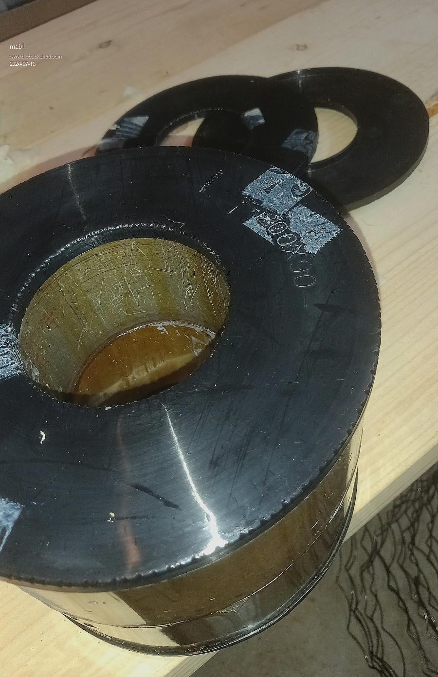 So that's 200 x 90 sure enough. That makes the iron x section 55 x 156 high = 8580mm2 |
||||
| KeepIS Guru Joined: 13/10/2014 Location: AustraliaPosts: 2177 |
I totally agree with you - if it were not for the beefy 93v winding wrapped around the core I would not have done it that way- following your great build closely  _ Edited 2024-07-13 10:43 by KeepIS NANO:Inverter V 8.2ks - Linux AvrDude GUI script V4.1 |
||||
| Murphy's friend Guru Joined: 04/10/2019 Location: AustraliaPosts: 678 |
The 7 strand post may be what I wrote, it works well enough with 1.5 or 1.8mm wire. I would not attempt it with 2.8mm wire, 3 strand for that if I did it. You would need a pulley system to keep the wire strands taught as you twist them (with a battery drill). Re cycled twisted enameled copper wire is a good use for a parallel primary, wound one at a time and connect the ends to a small bus bar - I did that with 3 parallel's. Sometimes that's the only way to get the required turns with a decent cross section through the hole - unlikely in your case though. BTW, looking at that puny plastic core endcap I think you'll get a much nicer (and easier to wind tight) corner for the wire with 6mm plywood disks. You might need a wire grab tool to pull that 2.8mm wire snug. You can see my idea of that in my (tinker) warpinverter thread. |
||||
| mab1 Senior Member Joined: 10/02/2015 Location: United KingdomPosts: 282 |
Thanks . I may try and find some pulley sheaves like yours for straightening - not done anything with the kinky wires yet. Ah yes your wire grab tool: i did see that, and was wondering if i could make something like it out of wood - though i was thinking of being able to stop and rest my fingers without my windings unravelling .As for twisting wires together - I think I'll wait to see how the secondary goes on first. I was thinking about winding a test primary on the double stack when i realised I'd made a glaring error when i thought my secondary would be 61T on the double stack:- 61T would mean 4v per turn and a primary of 6 or 7 turns? For 48v? Wiseguy was estimating double that!  But I've worked out where I went wrong: i was thinking 121 turns on a single core = 61 turns on the double, but i was forgetting that 121 turns gives me 115v per core, and series connecting them in a keepIS stack for 230v. If i want 230v from my double core i still need 121 turns  , or thereabouts. , or thereabouts.So I've done some variac measurements: 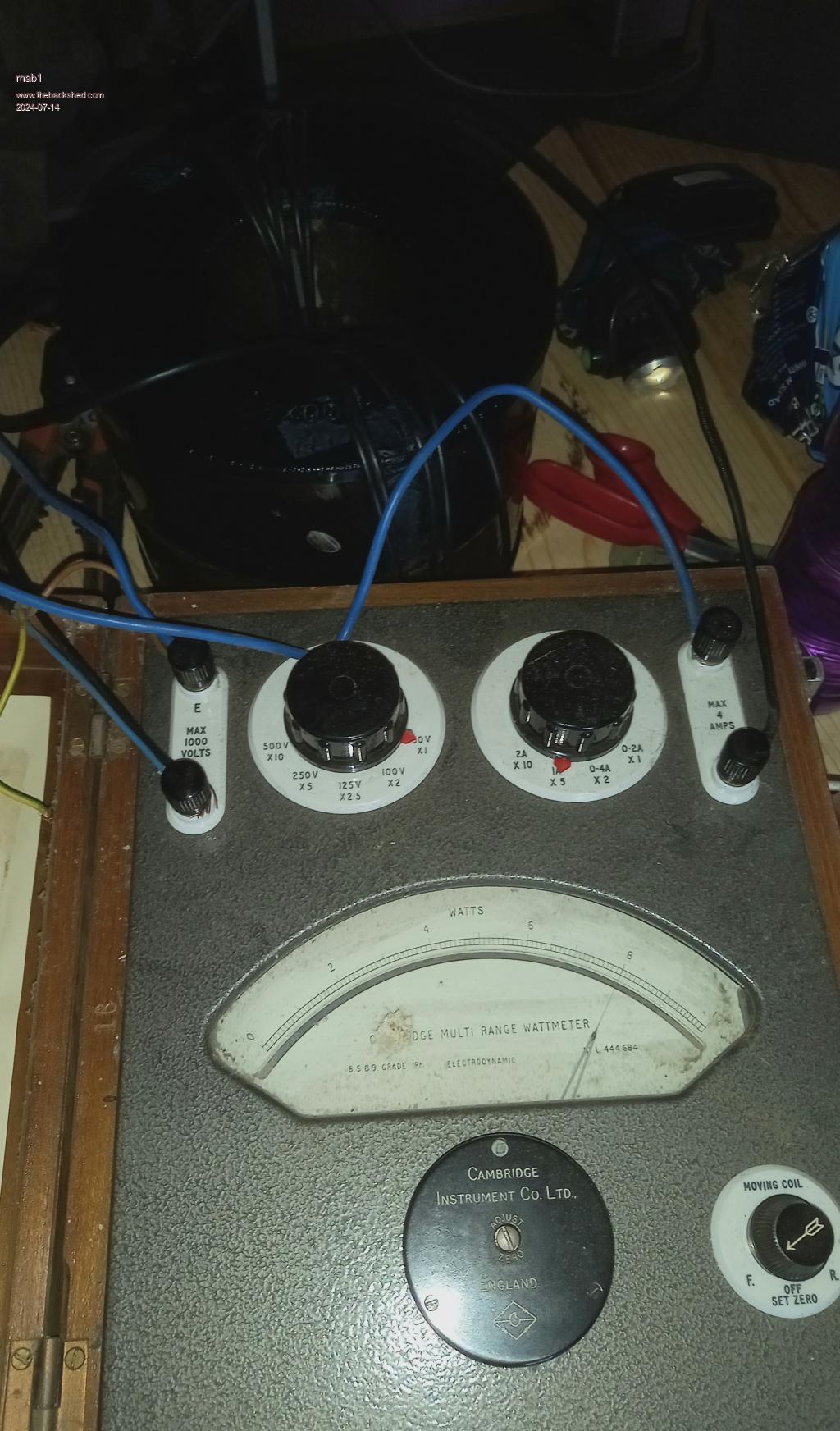 And even made some fancy charts:- 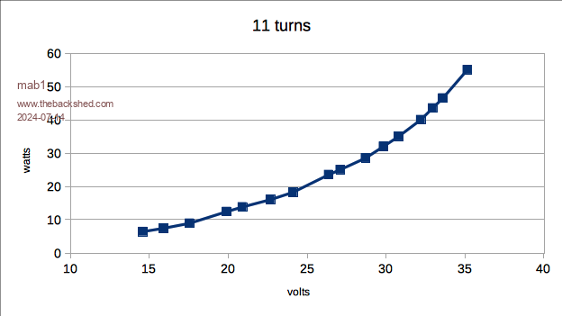 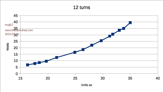 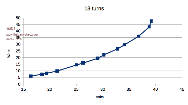 Then i realised i was just duplicating the same data: so i put it all on one chart scaled in volts per turn. 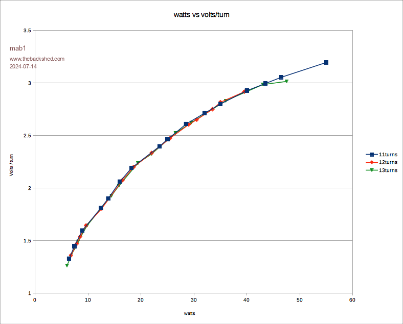 There's the odd dodgy result:- the diversion controller was turning the 3kw immersion on and off and if it switches between my reading the wattmeter and the voltmeter there'll be an error (if only i had a variac that didn't vary it's output volts with input ) |
||||
| Murphy's friend Guru Joined: 04/10/2019 Location: AustraliaPosts: 678 |
Wire grab tool, you'll need some very hard wood (oak?) or it soon will wear a groove in it. Regarding letting go of the wire for a rest, with 2.5mm diameter there is little chance of unravelling. But you will have trouble to wind tight against the inside of the hole where space *really* matters. I used a thick dowel to push the wire out, winding direction was coming up the hole and over the top. Make sure there are no cross overs on the underside where you can't see it and the core is too heavy to lift and check for that .A suggestion; you might make provision for various distances between your 3 straightening sheaves. More distance to start removing kinks and less as the wire gets straighter. |
||||
| mab1 Senior Member Joined: 10/02/2015 Location: United KingdomPosts: 282 |
Ok, i can see i need to put some thought into winding tools: a big dowel or something for getting the wire straightish through the cores, a puller (something hard enough to resist wear but soft enough to not damage the enamel). And possible a mallet for making the corners? And possibly a winding hoop. Who's idea was it to do this properly?  Oh, yeah - mine Oh, yeah - mine |
||||
| rogerdw Guru Joined: 22/10/2019 Location: AustraliaPosts: 955 |
Mab, I have a set of plastic spring clamps I bought as a set ... like large clothes pegs except rounded arms. Imagine a side view of your thumb and fingers grasping something. Anyway, you can clamp and hold the wire any time you want a rest ... and being plastic and having "feet" on each end that pivot to grip the surfaces ... it worked a treat. The largest one was big enough to clamp over my large warpverter transformer ... so it was a great investment and not even particularly expensive. I'm not sure if others do it this way ... but I simply use my fingers to keep the wire taut ... then bend it backwards away from the surface its going to cover ... then pull it around the corner. That stops the natural tendency for the wire to barrel out on the "flats". Bending the wire is what causes a lot of pressure on the thumbs ... but it prevents needing to pull the wire super tight. I had looked at Klaus's wire puller but decided I didn't need to pull particularly tight at all ... and mine have all held together really well as I've wound. You'll probably come up with your own techniques and do an even better job ... it's not really all that hard. Just needs a bit of patience. One other tip that helped enormously was to mark out a template for the first layer. I used a graphics program to draw all the "spokes" and printed it, cut it out and stuck it to the core. Then I simply wound each turn on top of the lines ... and it stayed super neat. Any subsequent layer then sits in the groove from the first layer and is super simple to wind and stay neat as well. Cheers, Roger |
||||
| mab1 Senior Member Joined: 10/02/2015 Location: United KingdomPosts: 282 |
Thanks for that - i think i know the sort of spring clamps you mentioned though i don't know what they're called. I'm probably overthinking things as usual, and will just have to try and see what works. Ive still got to straighten the wire, glue the cores together, and i probably should do some sort of spacing template - although I'm not actually a neat person so it'll probably end up looking a little organic TBH |
||||
| rogerdw Guru Joined: 22/10/2019 Location: AustraliaPosts: 955 |
Here's a couple pictures that give more detail. I had the same problem going over the whole process in my head ... it was only when I got off my butt and out to the workshop that I made really decent progress. And a lot of the issues I was worrying about became non-issues ... and some new ones appeared that were still relatively easily solved. Keep at it, you'll get there. Cheers, Roger |
||||
| Godoh Guru Joined: 26/09/2020 Location: AustraliaPosts: 664 |
Yes I used the same sort of clamps as Roger did. Woodworking clamps made of plastic with soft caps on the jaws. They work fine when you need a rest, just put the clamp on the transformer and the wire stays put. Pete |
||||
| mab1 Senior Member Joined: 10/02/2015 Location: United KingdomPosts: 282 |
Couple of stupid questions on capacitors (I'm still gathering parts):- Monolithic caps are the same as ceramic?(that's what google tells me)? On wiseguys BOM for the power boards, the big snap in electrolytic caps are suggested as 4700uF to 10000uF - this is a bit unspecific for my brain. As I'm going to have to buy new caps (used up almost all my 2nd hand ones on the mppts) I've got to choose some, and I'm struggling to decide on cost vs uF vs esr vs max ripple vs temp. If I'm trying to save on cost, as long as they're >=4700uF and >=63v, should i prioritise esr, ripple or uF?? Or just the cheapest? (My guess would be max ripple amps)? |
||||
| wiseguy Guru Joined: 21/06/2018 Location: AustraliaPosts: 1296 |
The snap in electrolytic capacitor PCBs allowing for 4 Capacitors per side was a bit like having a 2 way bet. You could use 1 or 2 expensive - low ESR high ripple types or up to 4 more inferior types to achieve a level of bulk storage and relatively low ESR to suit your parts bin or wallet. The thickness of wiring and impedance from your complete series circuit between battery interconnections and to the outside world, through fuse, circuit breaker, contactor, longish leads to the Power PCB - which is demanding an ultra low impedance each switching event, all play a part in what is the right value of capacitor/s to use. There is also inherent inductance as well as resistance in the wiring back from the inverter Power PCBs. So with a relatively short cabling run with adequately sized short interconnections the low impedance from the battery is less compromised so the requirement for local bulk storage and low ESR of the capacitor bank is less onerous. I consider that around 10,000 to 15,000uF is probably a reasonable starting figure for a typical installation and better spread over at least 2 relatively low ESR capacitors each PCB. My guess is that each capacitor is unlikely to cost less than ~ $5USD and an upper spend of 10 - $15USD should provide very adequate capacitors. 63V or 80V types should be used. I also think you should buy a minimum of 8 (10 might be cheaper). Values should start at 4,700uF and up to 10,000 - 15,000uF ea. If the capacitor is available in 2 housings the taller thinner body types usually have a lower ESR and dissipate heat better than short fat types. Ensure the capacitors outer diameter will allow the whole 4 to be loaded if required. DO not buy capacitors from Ali and Ebay etc do use Digikey, Mouser, Element14 etc as reputable suppliers anything else is false economy. 105 degree types are often specified for switchmode applications but I have found that 85 degree types with low ESR are quite adequate for the inverter, if you are in a milder climate even better. The cooler environment the capacitors live in will reward you with the best lifetime, so a ventilation fan breeze above 40 to 50 degrees is a good investment. I would start by loading 2 capacitors into each capacitor PCB and try the inverter with at least 2.5 - 4kW of load for at least 15 - 30 minutes and during that time feel the capacitors for self heating. the surrounding hardware and connections will get warm along with the capacitors but nothing should be getting a rapid heat rise in this process. A correctly sized choke that is well away from the saturation curve helps and not having too large an AC capacitor on the Toroids output also helps in the process to minimise heat build up. Unfortunately at this stage I cannot nominate a proven method to correctly size the capacitors due to the variability of builds and capacitor types used. But empirically is not a bad way to go either, why put 4 caps on the board if 2 run just as cool as 4. A good rule of thumb though is the more series impedance of the external wiring to the battery source, the higher amount of local bulk storage of low impedance capacitors is required for best performance. Edited 2024-07-19 10:59 by wiseguy If at first you dont succeed, I suggest you avoid sky diving.... Cheers Mike |
||||
| The Back Shed's forum code is written, and hosted, in Australia. | © JAQ Software 2026 |
