
|
|
Forum Index : Microcontroller and PC projects : RPZ Compute module
| Author | Message | ||||
| Mixtel90 Guru Joined: 05/10/2019 Location: United KingdomPosts: 8913 |
So, that's a ESP8266-01S version done. RPZ COMPUTE ESP Has a RP2040-Zero with a ESP8266-01S wireless modem module connected to COM1. The ADC connector and GP11-GP14 are omitted. GP15 is connected to the INT signal. Buttons are provided for the RST pin and IO0 to assist with programming.IO2 is brought out on GP11 pin of the module and IO0 on GP12 pin. If anyone wants any of the modules in this series, or would like me to produce another version, please let me know. I'm not publishing further design details at the moment as I'm still playing (as you may have noticed...). :) I'm considering putting four modules together on a single PCB so that one order will get you five of each. Probably the original, VGA, BT and ESP but I'm open to any ideas. Unfortunately I can't really get any more than four on - and you'll need to cut them, although JLCPCB would almost certainly cut the notches for the RPX2040-Zero. Mick Zilog Inside! nascom.info for Nascom & Gemini Preliminary MMBasic docs & my PCB designs |
||||
| Volhout Guru Joined: 05/03/2018 Location: NetherlandsPosts: 5945 |
Hi Mock, Just show the nice green top view board pictures. No need for Gerbers until interest. That will get them excited... For the ESP: it needs far more 3.3V power than the regulator on the ZERO can deliver.... Volhout Edited 2024-06-25 18:30 by Volhout PicomiteVGA PETSCII ROBOTS |
||||
| Mixtel90 Guru Joined: 05/10/2019 Location: United KingdomPosts: 8913 |
The ESP is specified as taking a maximum of 170mA. I've included for an electrolytic cap on the 3V3 rail to help with higher current spikes. The regulator on the RP2040-Zero is the RT9013, which is rated for a minimum of 400mA (under ideal conditions!). Allowing for around 50mA for the Zero, that should probably allow at least 200mA comfortably for the ESP. There'll be just about nothing spare for any external loads, but it would be ok for using the GP pins as inputs. I'll sort out some piccies. :) Mick Zilog Inside! nascom.info for Nascom & Gemini Preliminary MMBasic docs & my PCB designs |
||||
| Mixtel90 Guru Joined: 05/10/2019 Location: United KingdomPosts: 8913 |
Piccies! 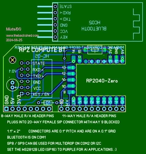 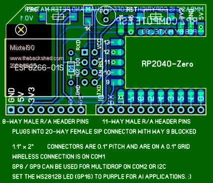 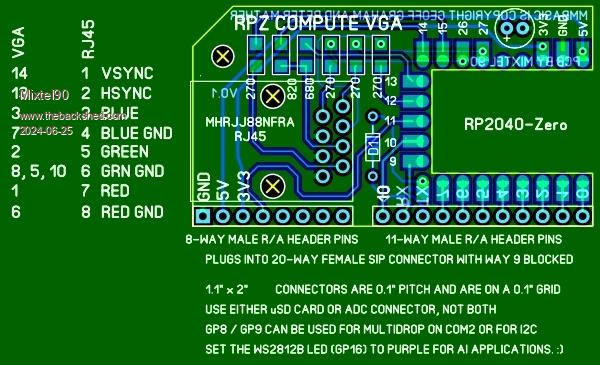 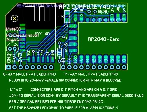 The others look very similar to the pics already posted so I won't repeat them. Mick Zilog Inside! nascom.info for Nascom & Gemini Preliminary MMBasic docs & my PCB designs |
||||
| Volhout Guru Joined: 05/03/2018 Location: NetherlandsPosts: 5945 |
Hi Mick, 170mA + 50mA = 220mA (pico = 50mA when running 133MHz) 5V - 3.3V = 1.7V 1.7V * 220mA = 375mW 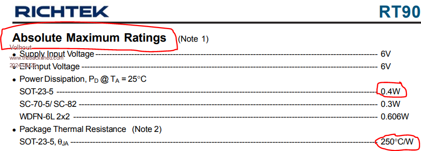 It is within spec, but I would not rely on it. It will get extremely hot, and when it reaches thermal shutdown, you will loose both WIFI and Pico, or they run very unreliable. Volhout Edited 2024-06-25 19:31 by Volhout PicomiteVGA PETSCII ROBOTS |
||||
| Mixtel90 Guru Joined: 05/10/2019 Location: United KingdomPosts: 8913 |
Oh well, it is what it is. :) There's no way to get it's own regulator on there. The only place for it is directly under the antenna, which isn't going to help the range in the least. Of course, you *should* be running it at lower power to keep within most countries RF regulations... As I've never had any success with these anyway I'm not too fussed. It's unlikely that I could test it. lol ------------------------------ Having said all that, here's V0.11 with added LM1117 goodness. (Yes, I wrote the wrong number on the silkscreen! It's not important, the connections are right.) The antenna ends up about 10mm away from the back of the Zero so it might be ok. 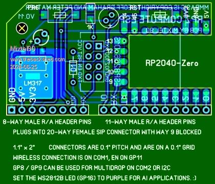 . Edited 2024-06-25 22:36 by Mixtel90 Mick Zilog Inside! nascom.info for Nascom & Gemini Preliminary MMBasic docs & my PCB designs |
||||
| Volhout Guru Joined: 05/03/2018 Location: NetherlandsPosts: 5945 |
Hi mIck, Just received my first ZERO, and it is running AI...;) 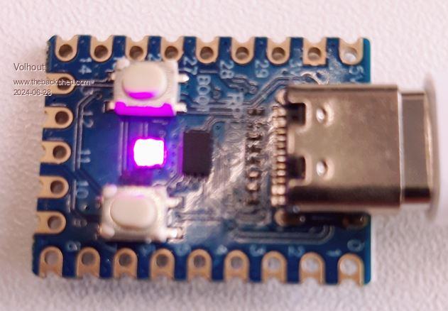 Volhout PicomiteVGA PETSCII ROBOTS |
||||
| Mixtel90 Guru Joined: 05/10/2019 Location: United KingdomPosts: 8913 |
Oh yes, they are good at that! :) But why, oh why does it have castellated holes when it's so awkward to surface mount, and the YD-RP2040 would be great for surface mounting if it had castellated holes? Sometimes I just can't win. :) Mick Zilog Inside! nascom.info for Nascom & Gemini Preliminary MMBasic docs & my PCB designs |
||||
| lizby Guru Joined: 17/05/2016 Location: United StatesPosts: 3788 |
First time seen in the wild?  Dim p(7)=(1,2,4,5,6,7,9,10) For i=0 To 7 Print p(i);" "; SetPin p(i),dout Next i Do For i=0 To 7 Pin(p(i)) = Rnd() '.5 rounded up: off or on Pause 500 Next i Loop PicoMite, Armmite F4, SensorKits, MMBasic Hardware, Games, etc. on FOTS |
||||
| Mixtel90 Guru Joined: 05/10/2019 Location: United KingdomPosts: 8913 |
Yep, AFAIK that's the very first. It looks rather cute. :) Mick Zilog Inside! nascom.info for Nascom & Gemini Preliminary MMBasic docs & my PCB designs |
||||
| DaveJacko Senior Member Joined: 25/07/2019 Location: United KingdomPosts: 103 |
YES.. ticks many boxes for the experimenter, always good if you can turn a DIP into a SIP ** maybe possibly improved if you could put the RPZero onto a socket.. don't know about you, but I often seem to brick things.. I don't like killing anything, including microprocessors Thanks for your work! Try swapping 2 and 3 over |
||||
| Mixtel90 Guru Joined: 05/10/2019 Location: United KingdomPosts: 8913 |
That version of the Zero is the cheapest one from AE, which is why the PCB is notched out. I considered using a socket for it but TBH I don't think it's worth the hassle. The idea was to have something as reliable as is reasonably possible - it could even be used for small industrial stuff. That's why there is a hole. A rod can be threaded through that to an angle bracket at each end to lock the modules into their sockets. Getting rid of a layer of headers does two things, it increases reliability and it reduces the "thickness" of the module so that they could be packed closer together. The design for the bus only has 3 modules across about 100mm of width, but that's because of the IDC connectors that I used. There are almost certainly narrower alternatives. You can add bus modules end to end though. Mick Zilog Inside! nascom.info for Nascom & Gemini Preliminary MMBasic docs & my PCB designs |
||||
| Mixtel90 Guru Joined: 05/10/2019 Location: United KingdomPosts: 8913 |
I'm putting together two 100x100 boards with multiple modules on them. They'll need cutting. It'll be a very cheap way to set up some experimental setups. Board 1 has a 3-slot expandable motherboard and a RPZ compute module Board 2 has Bluetooth, ESP8266, VGA (over RJ45), a short board with indicator LEDs and one spare position at the moment. Now, what do I populate the spare position with? There is a choice of: 1 - JDY-40. One of my favourites which is a wireless modem in this case (no access to the GPIO pins). 2 - isolated COM (like a MIDI interface). I thought this might be an interesting substitute for RS-485 over shortish distances, with the bonus of isolated supplies. Those are the only other options I've come up with at present. Unfortunately I can't quite get 6 modules on a 100mmx100mm board, only 4 and a short one (which isn't long enough for a Zero to be useful). Doing a third board shoves the cost up. I've not priced it up yet, but I wonder if it would be worth trying all the lot on a single board? Mick Zilog Inside! nascom.info for Nascom & Gemini Preliminary MMBasic docs & my PCB designs |
||||
| Volhout Guru Joined: 05/03/2018 Location: NetherlandsPosts: 5945 |
Hi Mick, I think I am in no way qualified to suggest a way forward, but if this is meant to be used in an industrial environment, I would focus on having IO that prevents ground loops and prevent electrical shock. Since the main controller can be VGA, the main controller is per definition earthed through the VGA cable/monitor. This leads to a requirement for isolated IO, unless the monitor is powered from an isolation transformer, but then still it is electrically wired to the IO ground. Maybe you should communicate to the main controller through an isolated RS232, or bluetooth (wireless) or JDY-40(wireless). In that case you would best use the USB version developped for CMM1.5 to get console at UART pins. I am sure these thoughts have crossed your mind several times already, so I am just duplicating your thoughts... Volhout Edited 2024-07-22 20:01 by Volhout PicomiteVGA PETSCII ROBOTS |
||||
| Mixtel90 Guru Joined: 05/10/2019 Location: United KingdomPosts: 8913 |
Just got a price of £12.06 for boards with everything on, including postage. It's all just for playing really, Volhout. It would have to be far more rugged as a proper industrial controller, I think, but for small, simple things it might be ok. As a controller I'd expect it to run alone - there's no keyboard or terminal interface as such by default. The VGA connection is only for a display. A wireless connection is perfectly possible as all the modules can be a master and have control of the COM/I2C bus. For a wired connection the "MIDI" connection gives full duplex to a COM port so it could be configured as a console connection. I'm not going to bother with isolated IO. That can easily be added on the end of ribbon cables plugged into the motherboard (the modules aren't really designed to be used alone, although it's perfectly possible). You can opto-isolate to anything then. Likewise I'm not considering the USB version. It doesn't really fit in with my concept - it isn't a computer, it's more like a PLC with the possibility of distributed IO. Typical arrangement: Board 1 runs the process and has a Compute as master and a ESP that's linked to a local network Board 2 in a different building has a ESP as master and two computes which are providing IO Board 3 is a process indicator, with another ESP and a VGA A CMM2 Gen 2 is used for overall control, linking to Board 1 using its ESP from an office UPDATE: The JDY-40 now has pins GP01, GP02, GP03, GP04 and GP05 brought out on the GP10, GP11, GP12, GP13 & GP14 pins of the IDC connector. GP08 drives an LED as before. This allows it to be used as a remote control by operating pins GP01 to GP05 to get a remote device to operate its pins. This operates independently of the Zero. It can also receive a byte and bits GP01 to GP05 can be fed into GP pins of the Zero. Of course it can still operate as a 2.4GHz wireless modem too. Edited 2024-07-22 21:47 by Mixtel90 Mick Zilog Inside! nascom.info for Nascom & Gemini Preliminary MMBasic docs & my PCB designs |
||||
| lizby Guru Joined: 17/05/2016 Location: United StatesPosts: 3788 |
£12.06 for 5 with everything on a single board, or $4USD x 2 PCBs (£6.19) for 2 100mm x 100mm designs? I'd go with the two separate boards. PicoMite, Armmite F4, SensorKits, MMBasic Hardware, Games, etc. on FOTS |
||||
| Mixtel90 Guru Joined: 05/10/2019 Location: United KingdomPosts: 8913 |
If you do it as two separate boards you can't get one of the modules. Also, if you put the two on a single order only one of them gets the special offer price. I still need to sort out the cost for that. I'm getting $13.29 for two boards on the same order including shipping. Why it's not in £ I don't know! About £10.28 at the moment. Edited 2024-07-22 22:07 by Mixtel90 Mick Zilog Inside! nascom.info for Nascom & Gemini Preliminary MMBasic docs & my PCB designs |
||||
| lizby Guru Joined: 17/05/2016 Location: United StatesPosts: 3788 |
My solution so far: place 2 orders. $4 per order with shipping and PayPal payment. PicoMite, Armmite F4, SensorKits, MMBasic Hardware, Games, etc. on FOTS |
||||
| Mixtel90 Guru Joined: 05/10/2019 Location: United KingdomPosts: 8913 |
Ah, but which module would you omit? :) Mick Zilog Inside! nascom.info for Nascom & Gemini Preliminary MMBasic docs & my PCB designs |
||||
| zeitfest Guru Joined: 31/07/2019 Location: AustraliaPosts: 683 |
Just a thought - how would these go adopting a "Click" format small module connecting on the "Mikrobus" bus ? |
||||
| The Back Shed's forum code is written, and hosted, in Australia. | © JAQ Software 2026 |
