|

|
Forum Index : Microcontroller and PC projects : Pico Gamer
| Author | Message | ||||
| SimpleSafeName Guru Joined: 28/07/2019 Location: United StatesPosts: 319 |
Looks great!! |
||||
| Andrew_G Guru Joined: 18/10/2016 Location: AustraliaPosts: 847 |
Geoff, Well done! SimpleSafeName, following our 'conversation' a month or two back I bought an AnkerMake 5 and I am very happy with it. I use OpenScad and can do simple things. I can 'IMPORT' Geoff's STL file (thanks Geoff) but all I get is the complete item - without the ability to edit or remove features - am I missing something? (I use the AnkerMake slicer and it slices it OK but complains about the raised lettering. I have a smooth build plate so I can get smooth bottom layer). Cheers, Andrew |
||||
| SimpleSafeName Guru Joined: 28/07/2019 Location: United StatesPosts: 319 |
Excellent! I'm happy to hear that! :) You can't (as far as I know) edit an "external" .STL file per se. But what you can do is to import it and add and/or subtract from that .STL file. So you end up editing it in a backdoor sort of fashion. Here's an example of importing a .STL and then adding the OpenSCAD elements to it (or in this case subtracting "stuff" from the original model). I've included the files for you to play with. Enjoy. :) OpenSCAD Merge Example.zip $fn=64; //difference() { translate([0,0,0]) import("HextrudORT_Dragon_TENSION_ARM_body_V1.5.STL"); difference(){ translate([4.425,-15.09,2.9]) cylinder(r1=2.25, r2=2.25, h=14); translate([4.425,-15.09,2.4]) cylinder(r1=1.75, r2=1.75, h=15); }; difference(){ translate([4.425,-15.09,2.9]) cylinder(r1=4.25, r2=4.25, h=14); translate([4.425,-15.09,2.4]) cylinder(r1=3.75, r2=3.75, h=15); }; difference(){ translate([6.9,-5.6,2.9]) cylinder(r1=2.25, r2=2.25, h=14); translate([6.9,-5.6,2.4]) cylinder(r1=1.75, r2=1.75, h=15); }; difference(){ translate([6.9,-5.6,2.9]) cylinder(r1=4.25, r2=4.25, h=14); translate([6.9,-5.6,2.4]) cylinder(r1=3.75, r2=3.75, h=15); }; |
||||
| Martin H. Guru Joined: 04/06/2022 Location: GermanyPosts: 1113 |
So that I have a smooth contact surface when printing I wanted to change the lettering of the TOP Cover from raised to engraved. Top Case: Base For a simple housing, that's a lot. Sadly I could not Handle such complex files. 'no comment |
||||
Chopperp Guru Joined: 03/01/2018 Location: AustraliaPosts: 1057 |
OK, I tried importing the STL file (after reading up & watching a Vid on how to do it), but nothing comes up in the main window. The console seems happy. I tried other files, but get the same blank display. I did a "Check Validity" which said "No" so there must be something wrong with the import. A file I render locally validates OK. Brian ChopperP |
||||
| SimpleSafeName Guru Joined: 28/07/2019 Location: United StatesPosts: 319 |
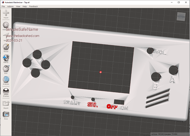
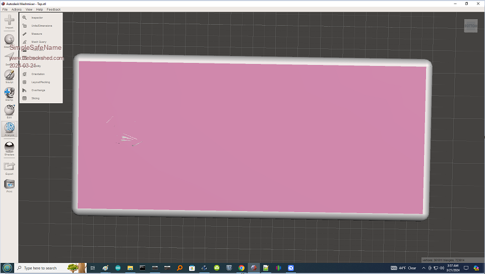
Oh what fun! OpenSCAD is correctly complaining about an "ERROR: The given mesh is not closed! Unable to convert to CGAL_Nef_Polyhedron." error. This has happened to me in the past when I was trying to print the Destiny Thorn gun that someone had added their name to in the model. So until the error is fixed OpenSCAD won't render the file (and without a proper rendering, there will be no STL file exported). So, off to MeshMixer. Which shows where the error is:  And MeshMixer's first shot at fixing the error:  Arguably it did fix the problem. LOL! Nonetheless, it appears that we have some work to do. :) The best thing would be for Geoff to remove the text, but I'll muck about with it and see if I can fix it. My edits might leave a file that looks correct, but no longer prints accurately (but I don't expect that to happen). So take this post as a work in progress, |
||||
| Geoffg Guru Joined: 06/06/2011 Location: AustraliaPosts: 3194 |
There seems to be some confusion going on here. Probably a case of the blind leading the blind (at least I know that I'm rather blind in this discipline). Firstly, I intended for the case to be made by a commercial company (ie, jlc3dp.com), not a home printer. I have never used a home printer but my guess is that it would not work out very well - the STL files are complex, home printers have a rough surface finish, etc. BTW, one of the reasons for such a complex STL file is that I was after a very smooth bevel on the corners of the case so that it would sit comfortably in the user's hands. Also, I have only used Blender. Other packages seem to work in a completely different fashion. My recommendation to use Blender was solely based on the fact that I was able to get it to work after a steep learning curve. Finally, the raised letters works well - easy to read but not annoying. However, for anyone who needs it, I have created a version without the lettering (top enclosure only). It can be downloaded from here: https://geoffg.net/Downloads/picogamer/TopNoLetters.zip. I was reluctant to make it available as I have not had a test piece made, so please be aware that there may be a defect in it (although I doubt it). Geoff Edited 2024-03-21 19:43 by Geoffg Geoff Graham - http://geoffg.net |
||||
| SimpleSafeName Guru Joined: 28/07/2019 Location: United StatesPosts: 319 |
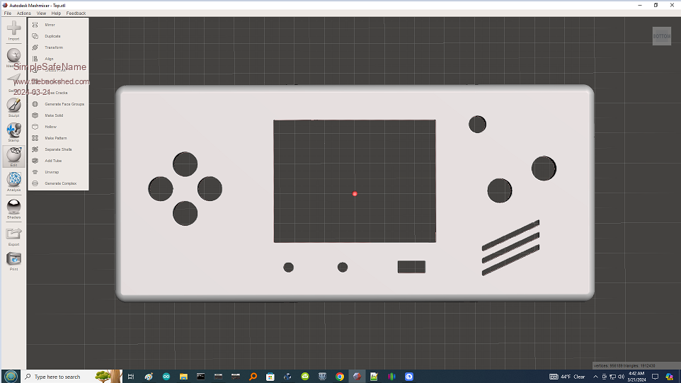
Yeah! Thank you! For the record, there is nothing wrong with your file - if - it is printed as you intended using a resin printer. But if you want to print it at home using a filament 3D printer the bumps from the letters will lift the rest of the print off of the build plate and that part of the print will begin in mid-air (which won't work). That's all that was "wrong" with it. But by editing your design to omit the lettering you fixed the problem for filament 3D printers. And it can now be printed at home. I did "fix" it in MeshMixer, but I've forgotten what I did to fix the previous file for my friend. The resulting file is about 3 times the size (but looks pretty good), but it now exceeds the memory limits of OpenSCAD (my rig has 64 Gig, I'm going to go out on a limb and say that *I* didn't run out of memory). But your file is the way to go. Here's what I ended up with in MM:  |
||||
| Geoffg Guru Joined: 06/06/2011 Location: AustraliaPosts: 3194 |
Thanks John, maybe in future I should indent the lettering. If you, or anyone, does print this on a home filament printer I would be interested in hearing about the experience (surface finish, accuracy of the features, strength, etc). Geoff Geoff Graham - http://geoffg.net |
||||
| Martin H. Guru Joined: 04/06/2022 Location: GermanyPosts: 1113 |
Thanks a lot  For People that like to print it with filament Printer, I changed the "No Text Version" to engraved text. PICO GAMER TOP-engraved text.zip Cheers Martin Edited 2024-03-21 23:48 by Martin H. 'no comment |
||||
| Geoffg Guru Joined: 06/06/2011 Location: AustraliaPosts: 3194 |
That's great Martin. Would it be OK if I added it to the construction pack? Geoff Geoff Graham - http://geoffg.net |
||||
| Martin H. Guru Joined: 04/06/2022 Location: GermanyPosts: 1113 |
Of course you can do that  'no comment |
||||
| karlelch Senior Member Joined: 30/10/2014 Location: GermanyPosts: 172 |
Steel, aluminium - pah! In the good old times, we hand-carved our cases from wood and wrapped them with leather!  Sorry - could not resist. Sorry - could not resist. |
||||
| SimpleSafeName Guru Joined: 28/07/2019 Location: United StatesPosts: 319 |
You're welcome! And for filament style 3D printers it would certainly be helpful. :) You could flip the part over so the lettering was on the top, but that would require adding support inside the void to get it to print (and support rarely comes away cleanly from the part it is intended to support). I did some more experimenting, and I found that I could "bury" the issue by setting the Z axis transform downwards by .5mm in the slicer. So if all you want to do is to print it out, then this would work in a pinch (and for any other prints that had the same problems). But thank you again for fixing this. :) I'm going to print it out on my printer just to see how it comes out. But if I make a Pico Gamer, I'll have the case printed by JLC3DP as you suggested. It does look stunning. :) But what I will do for a print on my printer, is to put a "pause" in the G-Code file once the print has got to the .5mm level. This would allow me to change the filament color to something different to make the indented lettering stand out. And I will probably print it in ABS and then use ABS "Vapor Smoothing" to give it a resin level of smoothness. And a bit of OpenSCAD "Inside baseball" concerning the error: This is twice now that text has "broken" the STL file for me. What happens is that the manifold is no longer watertight. It still prints, usually with no problems, but OpenSCAD can't handle the "leak". Here's what one of the guys had to say about what was going on "There are many, many ways to get this class of error. Roughly, they can be broken down into three sub-classes: * Polyhedra that are malformed - that have missing faces, faces oriented the wrong way, or self-intersections. * Polyhedra that have points that are too close together, that OpenSCAD snaps together when it forces everything onto its grid. * Models that are not 2-manifold, that have volumes that touch only along a single line." It's my understanding that the underlying STL engine, "GCAL", can allow a precision that will induce errors (how helpful...) and there's not much that the OpenSCAD team can do about it. https://github.com/openscad/openscad/issues/4039 Edited 2024-03-22 04:08 by SimpleSafeName |
||||
| SimpleSafeName Guru Joined: 28/07/2019 Location: United StatesPosts: 319 |
Nice! Thanks!! |
||||
| SimpleSafeName Guru Joined: 28/07/2019 Location: United StatesPosts: 319 |
Whaaa? You don't chisel them into the walls of your cave?!? |
||||
| Andrew_G Guru Joined: 18/10/2016 Location: AustraliaPosts: 847 |
Wow, A lot of dialogue on this overnight - I haven't caught up yet. Thanks to everyone for chipping in and to Geoff for being so understanding. We hadn't meant to hijack your 'release' of Pico Gamer. 3D printing is still a little of a black art - for example for about Au$50 I have a smooth 'build plate' (magnetic and with the normal rough surface on the reverse). This gives a mirror-like finish to the bottom. Even with a 0.4mm nozzle I get pretty good finish elsewhere. A resin printer would be better again. Thanks again, Andrew |
||||
| damos Regular Member Joined: 15/04/2016 Location: AustraliaPosts: 63 |
That is my experience as well, although not sure about the easy part. It is very easy to use Blender the way you describe, but every time you go do something new, there is a whole extra learning curve, then you get a whole heap of extra capability and it keeps repeating. In my case I decided to take the design and render it. Light sources, cameras etc. Heaps of work, but wow!. Then I decided to animate it. It works really well, but once again, steep learning curves. I have done the full wood working, metal working, styrene modelling and then laser cutting, but at this stage 3D printing wins every time. All of the methods require as much time finishing as design and creating if you want a good result. For non-presentation work a quick clean up with a knife, file or sandpaper is all that is required for 3D printed parts. For example with LCD panels, my minimum standard is no visible screws if possible. To do this in a jiffy box it requires an accurate cutout with drilling, cutting and lots of filing. Then I glue styrene blocks to the back and drill holes to mount the panel to the back using 6mm self tapping screws. It gives a really good finish but takes a lot of time. I now have a design for Micromite backpacks and I just print it out. For most applications the box is good enough straight from the 3D printer - I would say similar in quality to a jiffy box. If I want a really good finish I can use a higher quality setting on the printer. Generally a quick sand and a coat of spray paint and you get a really good finish. If you use angled sides you can get a stepping effect that can be covered with filler (I just use gyprock filler as it really soft and easy to work). I think the best approach could be high-build spray putty. |
||||
| PeteCotton Guru Joined: 13/08/2020 Location: CanadaPosts: 368 |
This reminds me of the apocryphal Michelangelo quote: Congratulations on another very cool project.  |
||||
| IanT Regular Member Joined: 29/11/2016 Location: United KingdomPosts: 87 |
Interesting thread - both in terms of Geoff's new device and 3D printing/CAD. A friend recommended Open SCAD when I got my 3D filament printer a few years back. It was very easy to get into and will suit anyone with a programatic frame of mind. By using variables you can build models that are easily modified for size and fit. So it worked well in my workshop to produce hose adaptors and various small cases and containers where frankly, I don't care about surface finish. However, it didn't replace my engineering/drafting CAD which for many years had been 2D TurboCAD. So I finally bit the bullet and decided to learn a 3D CAD system. I settled on Siemens Solid Edge (Community Edition) which is a free download running on Windows (I have it on Win 10 & 11 Home Editions) locally (e.g. no Cloud required). I've been using it for about 3 years now and I'm very happy I invested the time learning it. Not everyone will have my technical requirements of course (dimensioned drawings, multiple export/import file types, fully parametric etc). I too recently had to import and modify a .STL file and SE has the ability to both repair the mesh and to (some extent) modify .STL files but it is (as mentioned by SSN) mostly to add or subtract material. The STL file doesn't have enough data to truely reconstruct the part but you can 'flatten' surfaces for instance, which then become more usable (e.g to mate/align another part to it). My file was of a locomotive wheel and I was able to clean up the hub and then remove the flange and replace it with a new one (designed in SE). So easier perhaps than starting from scratch but a .STEP file would be much better for this kind of re-cycling, as it contains more base data. As Solid Edge can be used for 2D drafting, it has replaced SCAD and TurboCAD as my sole CAD system, which makes life a little simpler. If you are looking for a full-fat 2D/3D CAD system then I'd suggest you look at Solid Edge CE. It's not as well known (publicised) as Fusion or FreeCAD but it's a very powerful CAD tool should you need one. OK - Sorry to Interupt, Back to lurking... IanT |
||||