|

|
Forum Index : Microcontroller and PC projects : For those too young to remember the CMM2
| Author | Message | ||||
| stanleyella Guru Joined: 25/06/2022 Location: United KingdomPosts: 2127 |
$4 ? can you get them? I got pickit3, looks easy youtube. what's the griff on mm over pico as for implementation? get chips from rs/farnell in uk or microchip? Edited 2024-02-25 07:58 by stanleyella |
||||
| Mixtel90 Guru Joined: 05/10/2019 Location: United KingdomPosts: 6786 |
The 28-pin MX170 is now about the same price as a normal price Pico (not a clone). Unless you have a specific need for the 28-pin chip the RP2040-Zero has a far better spec and is cheaper. It doesn't take up much more board space either, especially if you were going to fit a voltage regulator and USB-TTL converter as well. Mick Zilog Inside! nascom.info for Nascom & Gemini Preliminary MMBasic docs & my PCB designs |
||||
| PhenixRising Guru Joined: 07/11/2023 Location: United KingdomPosts: 858 |
Heck, no, as I stated, no problem with copyrights but I'm shooting for an industrial look but that banner.... |
||||
| stanleyella Guru Joined: 25/06/2022 Location: United KingdomPosts: 2127 |
I only asked cos so many references to micromite and how better than picomite. lots of mm code. converting? recommend use rpi pico? I'm liking usb vga picomite. |
||||
Grogster Admin Group Joined: 31/12/2012 Location: New ZealandPosts: 9306 |
@ Peter - Redesign sounds like a nice idea, but can you please continue to use the same plastic case and PCB mounting holes spec as the old board, so that the new board will still fit in the same case, as I have a whole stock of those cases now, and don't want to have to start buying another case.  The front/rear panels and layout are easy to change, so no issue there, just IDEALLY need you to stick to the same case please if possible. Good idea, if possible. However, I have had zero issues using standard 5mm spacers. I use a tiny bit of "Blu-Tak" on top of each mounting pillar in the case, and then push the spacer onto that. This keeps the spacers stuck to the mounting pillars long enough for you to settle the board into the case and secure it with screws. Smoke makes things work. When the smoke gets out, it stops! |
||||
| matherp Guru Joined: 11/12/2012 Location: United KingdomPosts: 9114 |
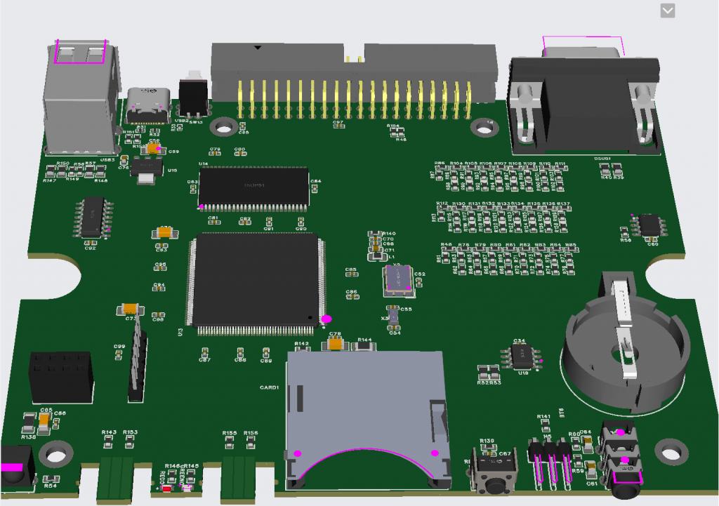
Absolutely, I've just imported the PCB outline from DesignSpark into EasyEDA. The basic objective is to get the layout onto a more modern platform and do some value engineering so: Remove as many as possible "extended" range components The PCB to be able to be built by JLC with NO extra components to be hand soldered Remove any redundant circuitry For example, if you look at the circuit it now uses pairs of 120ohm resistors in series to make 240. The 120s are "basic" whereas JLC don't list a basic 240. Instead of the expensive LED package the new design uses two SMD "side-sticker" leds. I didn't know these existed before but they are LEDs that shine out of one side rather than the top - perfect for the power and disk indicators. Later today or tomorrow I should have an unrouted layout I can cost at JLC so I'll post that when I have it. |
||||
| Mixtel90 Guru Joined: 05/10/2019 Location: United KingdomPosts: 6786 |
Interesting... 240R is a normal E24 series 5% and 2% value. It seems a bit odd to not have it in the basic range. Unless that range is 10%, of course. Mick Zilog Inside! nascom.info for Nascom & Gemini Preliminary MMBasic docs & my PCB designs |
||||
| matherp Guru Joined: 11/12/2012 Location: United KingdomPosts: 9114 |
Here is the new layout (still unrouted). The great news is the price £135 for 5 boards (not including postage and tax) fully completed as you see here - nothing left to solder and ready to pop into a box  Edited 2024-02-25 21:22 by matherp |
||||
| PhenixRising Guru Joined: 07/11/2023 Location: United KingdomPosts: 858 |
Beautiful  But is that uSD? |
||||
| matherp Guru Joined: 11/12/2012 Location: United KingdomPosts: 9114 |
No: The CMM2 firmware implements both card-detect and write protect so I decided to keep with a full size SD to aviod any conflicts |
||||
| Mixtel90 Guru Joined: 05/10/2019 Location: United KingdomPosts: 6786 |
That's a very clean looking layout. Good price too. Mick Zilog Inside! nascom.info for Nascom & Gemini Preliminary MMBasic docs & my PCB designs |
||||
| JohnS Guru Joined: 18/11/2011 Location: United KingdomPosts: 3801 |
I think there are things where the Micromite (PIC32) is better e.g. ADC, 5-volt tolerance. John |
||||
| JohnS Guru Joined: 18/11/2011 Location: United KingdomPosts: 3801 |
Amazingly good price! John |
||||
| Mixtel90 Guru Joined: 05/10/2019 Location: United KingdomPosts: 6786 |
The Micromite is different to the PicoMite, just as the CMM2 and Armmite are. They all run versions of MMBasic (which are not identical but very close in some cases). You can regard MMBasic platforms as complementary rather than "better" or "worse". It all depends what you want. :) Don't forget that that price has to have postage and taxes added. It will probably be closer to £200 for five boards delivered to the UK. It's still a very good price though. Mick Zilog Inside! nascom.info for Nascom & Gemini Preliminary MMBasic docs & my PCB designs |
||||
| LeoNicolas Guru Joined: 07/10/2020 Location: CanadaPosts: 479 |
This sounds like a required update for my CMM2 v1  |
||||
| Volhout Guru Joined: 05/03/2018 Location: NetherlandsPosts: 4228 |
For USBmice to PS2 we have a solution now. RP2040… costs mere 70 cents. Can be programmed through the usb connector, only needs boot switch or jumper and flash memory. You have these parts in your library Peter. Volhout Edited 2024-02-26 04:59 by Volhout PicomiteVGA PETSCII ROBOTS |
||||
| Turbo46 Guru Joined: 24/12/2017 Location: AustraliaPosts: 1611 |
I agree, It seems to be a retrograde step to go back to a PS2 only mouse plus it would add a potential point of confusion to use a USB socket for a PS2 mouse. One can always add on an adapter now, we have that solution too, but a tacked on afterthought does not appeal. For what it's worth. Bill Keep safe. Live long and prosper. |
||||
| matherp Guru Joined: 11/12/2012 Location: United KingdomPosts: 9114 |
The PS2 mouse support is there - it works perfectly - better than USB as it supports the scroll wheel and there are known good cheap mice available so by all means play with an external RP2040 but I won't be supporting it |
||||
Grogster Admin Group Joined: 31/12/2012 Location: New ZealandPosts: 9306 |
Excellent, Peter.  Very pleased about the case and the LED's on the front panel also, as they were too expensive - for what they were.  In all the CMM2 units I have built and sold, I just replaced that package, with standard LED's. I've got pretty good now, and bending the legs of the LED's to be exactly right to poke through the front panel.  Looks like the mechanical toggle switch for power, has been replaced with a tact-switch for a push-on, push-off kind of thing which I like. Is that a reset tact on the back edge? EDIT: Looks like push-in/push-out power switch on rear, and reset tact at the front. Ignore what I suggested above.  Edited 2024-02-26 09:04 by Grogster Footnote added 2024-02-26 09:10 by Grogster Oh, BTW - price: Excellent too. A good percentage of the cost of the current CMM2, is TIME required to solder on all the connectors, which does take a bit of time to do, and time is money, so that is all added to the price. Once the new design is done, that should allow us to not only still offer the CMM2 with all it's powerful features, but the price per unit will drop by quite a bit as I no longer will need to charge for my time to put on all the connectors etc, so this is looking good overall. Name for the new design? CMM2 Generation 3? Smoke makes things work. When the smoke gets out, it stops! |
||||
| Volhout Guru Joined: 05/03/2018 Location: NetherlandsPosts: 4228 |
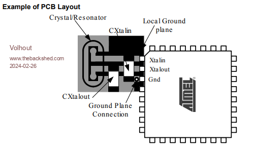
Hi Peter, I have not taken the time to dive deeply into the layout, but I notice one thing that could be critical in layout of the board. You have place the RBG resistor dividers close to the VGA connector. That is good for signal/noise on VGA, but as a result, you are running 24 high speed digital signals accross the board. And when I am right, these run along crystals X2 and X3. To avoid having the jittering VGA video (as the first blue Waveshare boards had) the crystals need very noise free environment. Ground plane under them, short traces to the STM32, surrounded by a guard trace (ground trace) to avoid any coupling into these crystal traces. Best is to have the ground plane under the crystals isolated from the ground plane, start connected to the ground plane under the STM32 ground pin nearest to the crystal oscillator pins. The 2 capacitors connect to that "crystal ground plane", not to the "noisy" board ground plane.  I hope I have not confused you, Volhout Edited 2024-02-26 17:50 by Volhout PicomiteVGA PETSCII ROBOTS |
||||