|

|
Forum Index : Microcontroller and PC projects : VGA socket
| Author | Message | ||||
| stanleyella Guru Joined: 25/06/2022 Location: United KingdomPosts: 2129 |
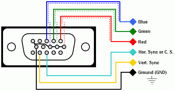
or cut the vga un needed leads and bend the 6 pins left?  |
||||
| Mixtel90 Guru Joined: 05/10/2019 Location: United KingdomPosts: 6787 |
Blue short style VGA socket here. Picture: You can get 15 of these out of a single 100mm x 100mm board. You get five boards per order from JLCPCB. These are the Gerber files for a single adapter. If you use these files you will get five little adapter boards. VGA121-1.zip These Gerber files will get you five 100mm x 100mm boards, each containing 15 little adapter boards. The problem is that you will have to cut them out yourself as they are only separated by screen printing. VGA121-15.zip It doesn't matter which option you choose, the cost is the same because you are paying for a single order with a minimum quantity of five boards of 100mm x 100mm or less. Have a look at the JLCPCB web site next and experiment with the "Upload a Gerber file" option. Until you press order you can play as much as you like. It will change the pricing dynamically. I suggest that you select the cheapest postage system when you come to order, unless you want your boards quicker. Mick Zilog Inside! nascom.info for Nascom & Gemini Preliminary MMBasic docs & my PCB designs |
||||
| stanleyella Guru Joined: 25/06/2022 Location: United KingdomPosts: 2129 |
I'm using the manual vga pins, this is my problem with other's pcbs. vga implementation is an effort for a one of board. each to their own method it seems.  |
||||
| Mixtel90 Guru Joined: 05/10/2019 Location: United KingdomPosts: 6787 |
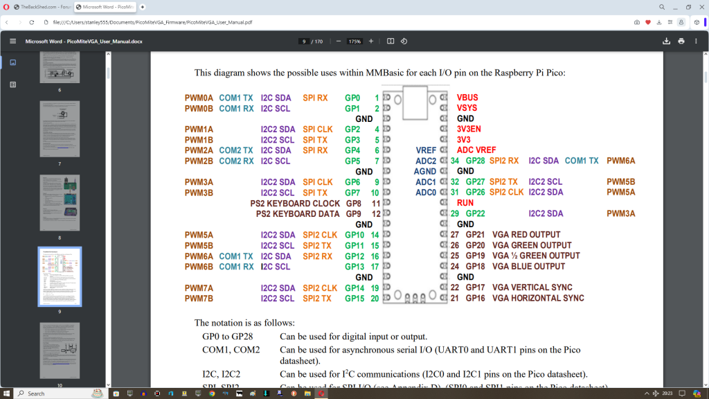
That board that I've done is intended to start at GP0. You can't have a board that will start at any pin unless you wire it. OPION VGA PINS lets you use other pins, but they still have to be 2 consecutive and 4 consecutive. With a Pico plugged into the end of a breadboard with the USB socket at the end my design plugs straight in and doesn't consume any extra space after GP5. It will also work starting from pin GP16 (the original VGA pins position) but it will restrict some access to breadboard pins off the back end of the Pico. Mick Zilog Inside! nascom.info for Nascom & Gemini Preliminary MMBasic docs & my PCB designs |
||||
| stanleyella Guru Joined: 25/06/2022 Location: United KingdomPosts: 2129 |
I use gp0,gp1 as audio as in the manual. if audio could be pwm3a,3b then usb to ttl, audio, vga all one side of pico. Edited 2024-02-21 12:05 by stanleyella |
||||
| Mixtel90 Guru Joined: 05/10/2019 Location: United KingdomPosts: 6787 |
The audio can be on almost any pair of PWM pins. See OPTION AUDIO. I often use GP6 & GP7 (PWM3). GP8 and GP9 (PWM4) are reserved for keyboard or USB console though. Mick Zilog Inside! nascom.info for Nascom & Gemini Preliminary MMBasic docs & my PCB designs |
||||
| fred777 Regular Member Joined: 01/07/2021 Location: United KingdomPosts: 57 |
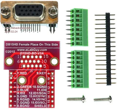
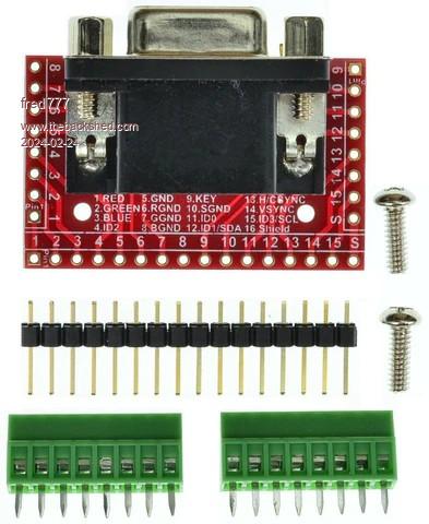
I have a couple of these VGA breakouts (both types), they work great on solderless breadboards and verboards. I only fitted the pin headers not the screw terminals. Btw that shop has similar breadboard breakouts for lots of other connectors (PS/2, USB, Serial, HDMI etc..) Shop elabbay   Edited 2024-02-24 03:47 by fred777 |
||||
| stanleyella Guru Joined: 25/06/2022 Location: United KingdomPosts: 2129 |
I like it, @fred777 the vga socket is a holdup for the diy beginner wanting picomite vga. using ili spi glcd is "easier" imho. if you're a tight git like me then I don't want to spend more than the cost of the picomite on an adaptor board :) I guess there's people can't solder and want an arduino type ready made board and there's some but a pico on breadboard with vga is a bit of thinking. not everyone got old graphic cards to rob. |
||||
| Mixtel90 Guru Joined: 05/10/2019 Location: United KingdomPosts: 6787 |
That board is $7.88. My board is about $4 for 5 if you do it the expensive way. Plus the cost of a VGA socket and some header pins & resistors. The sockets are about $1.50, I think, so one of my boards is a bit over $5.50 and it includes the resistors and plugs straight in without any extra wiring. You also have four spare boards. Mine is also smaller and can be fastened down onto 0.1" matrix board (all the pins and fixing holes are on that matrix). You don't need (or want) all the pins. The PicoMite doesn't support them. Edited 2024-02-24 08:08 by Mixtel90 Mick Zilog Inside! nascom.info for Nascom & Gemini Preliminary MMBasic docs & my PCB designs |
||||
| stanleyella Guru Joined: 25/06/2022 Location: United KingdomPosts: 2129 |
my vero was 5 for £5 odd free p+p. vga sockets scrounged. bit late now but should have used your pcb or similar for whole circuit, spi, sd card,i2c, etc. but like flexibility and only want 1 picovga for now. vero is between breadboard and a pcb. you can wave it around a bit without a reset. |
||||