
|
|
Forum Index : Microcontroller and PC projects : Programmable calculator on Pico DIY
| Author | Message | ||||
| Volhout Guru Joined: 05/03/2018 Location: NetherlandsPosts: 5940 |
Hi Zeitfest, Up to now I have followed your progress with interest. But I fail to see the benefit of an Arduino for display where the previous ILI9341 was just as fine... Are you running low on GPIO pins ? Volhout PicomiteVGA PETSCII ROBOTS |
||||
| Mixtel90 Guru Joined: 05/10/2019 Location: United KingdomPosts: 8911 |
I'm sure a standard Pico would be more than capable of handling the ILI9341 and a 24 or 32 button keypad with no further help. It can certainly do a 16 button scanned keypad as a background task. Couple that with context-sensitive buttons and it might be a simple build on a single pcb. Come to think of it, a RP2040-Zero has 20 GPIO pins, enough to scan a 16-button keypad (8 pins) and drive a SPI display (7 pins). Enough left over for a uSD card (4 pins) too!. :) I might try that and see if I can get it to fit ... Mick Zilog Inside! nascom.info for Nascom & Gemini Preliminary MMBasic docs & my PCB designs |
||||
| zeitfest Guru Joined: 31/07/2019 Location: AustraliaPosts: 683 |
Initially it was on a Silicon Chip Pico backpack, ie using a 3.5 inch 320x480 il9488 clone display using spi serial and other pins, the display was a bit awkward to use though. The 2.8 inch displays are a bit small so I dropped the backpack display and tried the Adafruit3.2 inch 240x320 il9341 /Uno and it is good. The advantage of using a I2C bus for the user I/O is that there is clean separation of tasks and a very easy 2 wire connection. Probably not fast enough for video etc but fine for a few data/text fields. Edited 2024-06-17 23:37 by zeitfest |
||||
| Mixtel90 Guru Joined: 05/10/2019 Location: United KingdomPosts: 8911 |
Just playing with a concept. Overall size is about 120mm x 72.5mm. 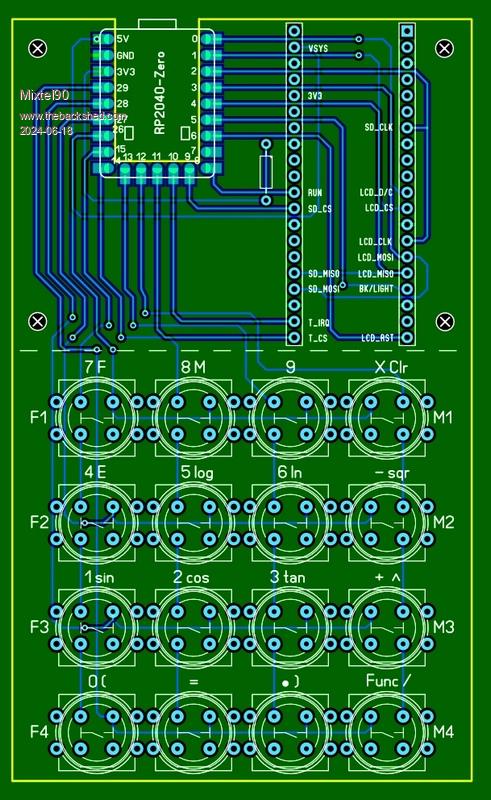 This board has male header pins onto which you plug a Waveshare Pico Res Touch 2.8 display. The RP2040 Zero obviously can't be plugged in under this because of height, so I've surface mounted it. Power is provided via the USB-C connector. I'm wondering if I could squeeze a rechargeable battery in. :) I've shown the keypad with two different sorts of buttons so it's a bit of a mess. It's just to see what will fit. The KS01 buttons are the round ones, the larger ones are the cheap Chinese "clicky" buttons, which can have round or square caps. Others could easily be used. Touch is supported, which might be handy for something like program selection. [Func] controls the keypad as 2-level, activating the alternative function for each key, so to get / you press the [Func] key twice. Pressing [Func] then F activates F1 to F4 function keys. Pressing [Func] then M activates M1 to M4 function/memory keys. The RP2040-Zero hasn't got a RUN input so GP8 is programmed as an active low interrupt input to reset the system. The keypad is scanned in the background, using the KEYPAD command. This scans the keys continuously and executes an interrupt on every key press. That routine decodes the press (via an array) and keeps track of a "keypad level" flag, which decides how the current key is going to be decoded. Edited 2024-06-18 00:37 by Mixtel90 Mick Zilog Inside! nascom.info for Nascom & Gemini Preliminary MMBasic docs & my PCB designs |
||||
| Volhout Guru Joined: 05/03/2018 Location: NetherlandsPosts: 5940 |
Hi Mick, As a calculator you would expect yhe display horizontal. Rotate the whole pcb 90 degrees cc. Then, after 90 cc, the keypad is not in right orientation(7,8,9 are at the left side, should be top side) This is just silkscreen.. Volhout Edited 2024-06-18 00:49 by Volhout PicomiteVGA PETSCII ROBOTS |
||||
| Mixtel90 Guru Joined: 05/10/2019 Location: United KingdomPosts: 8911 |
This is just playing. :) The display is landscape. The Waveshare module is fixed to this PCB using spacers in the four holes. Normally you would plug a Pico into the rear of the display module in a "vertical" layout with the LCD in landscape. I've designed the board to simulate a Pico. The pin arrangement you are seeing is from the top of my board, i.e. the mirror image of looking at the back of the Waveshare module. 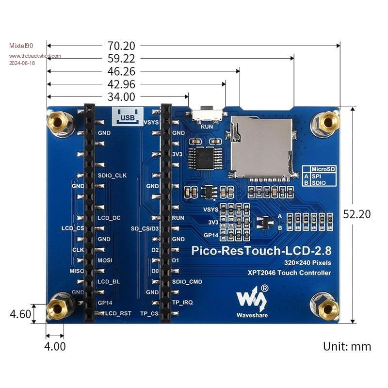 Mick Zilog Inside! nascom.info for Nascom & Gemini Preliminary MMBasic docs & my PCB designs |
||||
| zeitfest Guru Joined: 31/07/2019 Location: AustraliaPosts: 683 |
Sad reality is, basic calculators are $5 ... ie the calculator costs less than buying the keys  even the dual -line display type are maybe $8 - $12....full "scientific" maybe $30-40 and they are accredited for exam use...I even bought one as a donor keyboard (but the elastic key fronts don't glue well at all ). even the dual -line display type are maybe $8 - $12....full "scientific" maybe $30-40 and they are accredited for exam use...I even bought one as a donor keyboard (but the elastic key fronts don't glue well at all ). |
||||
| EDNEDN Senior Member Joined: 18/02/2023 Location: United StatesPosts: 295 |
Of course that is true. But for hobbyists this is a fun project to mess around with and do. Personally... I'm not really interested in making a basic calculator. But if this effort advances to the point where MuMath (or its equivalent) is running on the Pico I'm super interested. I would really like to see a full symbolic math package running on the Pico. Or stated a little differently... I would really like for the functionality of the TI Voyage 200 calculator to be Open Source and available for anybody to modify to suit their preferences. This how that kind of stuff happens. Incidentally... All the copy rights have expired on MuMath now. It is written in a Lisp derivative called MuSimp. For all practical purposes, anybody that knows Lisp can convert any Lisp interpreter to be MuSimp. Kind of like how the Forth language can easily be extended. And all the source for the symbolic math (Integrals, Derivatives, factoring and Matrix math) are easily available. My guess is a fully functional Lisp interpreter could be done in 10 or 12 KB of program space. Edited 2024-06-18 14:13 by EDNEDN |
||||
| Mixtel90 Guru Joined: 05/10/2019 Location: United KingdomPosts: 8911 |
"Ordinary" calculators for the bulk market are cheap. Specialised keypad input / colour graphic display devices aren't necessarily cheap, no matter what they do. :) Mick Zilog Inside! nascom.info for Nascom & Gemini Preliminary MMBasic docs & my PCB designs |
||||
| zeitfest Guru Joined: 31/07/2019 Location: AustraliaPosts: 683 |
Added a simple menu type display... calls up relevant program. Mashing some bugs (but looks better than the photo  ) )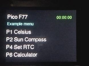 |
||||
| okwatts Regular Member Joined: 27/09/2022 Location: CanadaPosts: 67 |
Glad to see that progress is still ongoing, even with the 2 board solution. I'll follow along just to see where this is going. From my perspective there are 2 items of interest: (1) the software for the interpreter and (2) the implementation to the keyboard/screen. I know the ability to do graphics is limited with the 2 board approach and while this can be done in many ways on other platforms, it would be nice to have some graphical output. Even the low res of my HP48 calculator allows for some visual appreciation of the solutions. |
||||
| zeitfest Guru Joined: 31/07/2019 Location: AustraliaPosts: 683 |
Yes the graphical output on those calcs is nifty! At a few hundred dollars.. It would be possible to do a small indicative-result graph easily enough, but clearly it gets complicated very quickly and limited by i/o and memory, with limited use so is a bit moot. The screen has to be horizontal to hold a useful line of input, otherwise the user input has to wrap around to the next line - ok for scrolling text but lousy in equations. I also looked at putting a 6x6 keypad below the display, and it fits nicely into a "JiffY" but looks very clunky, bit like a old coin telephone  and I prefer the lateral format anyway. So the lateral layout with (6x5 and 6x1 keys) it is. and I prefer the lateral format anyway. So the lateral layout with (6x5 and 6x1 keys) it is.I now have set a pcb that holds the display and keys as above. Wondering about the pico and sdmicro socket, they may be better located separately somewhere in the case for the sd card access. Looks like there are pico variants wih sd socket / battery management etc so they might be good options(?) |
||||
| zeitfest Guru Joined: 31/07/2019 Location: AustraliaPosts: 683 |
Hmmm. Boxy but Practical. Practical but Boxy. It might have a use.  " Press button B..." maybe as a wall fixture 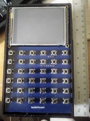 |
||||
| zeitfest Guru Joined: 31/07/2019 Location: AustraliaPosts: 683 |
The lateral/landscape pcb with the keypad, keypad IC module, display and display uno. It is all driven by an I2C connection. AS such it forms a I2C terminal. Here it is connected to a Pico via I2C, (a SC backpacK) and the four wires can be seen. Tho photo is a bit fuzzy sorry, it looks better in real life. 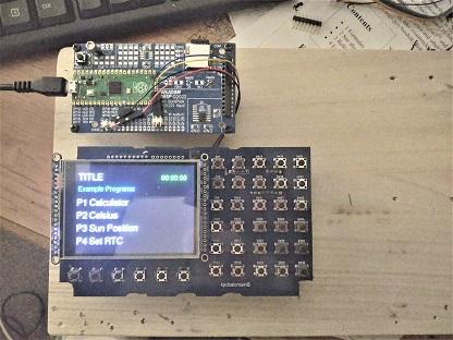 Now I am confident the implementation/hardware direction is solid. Edited 2024-07-23 00:50 by zeitfest |
||||
| zeitfest Guru Joined: 31/07/2019 Location: AustraliaPosts: 683 |
the other side with the tca8418 and uno 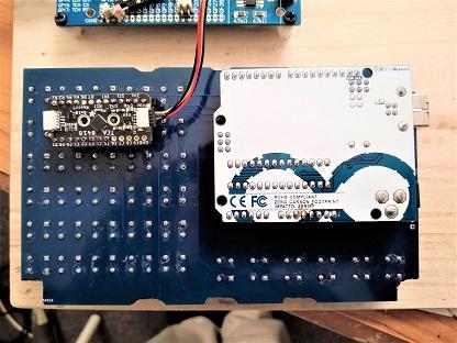 |
||||
| EDNEDN Senior Member Joined: 18/02/2023 Location: United StatesPosts: 295 |
Now we just need to get a full symbolic math package on it! |
||||
| Mixtel90 Guru Joined: 05/10/2019 Location: United KingdomPosts: 8911 |
I suspect the people that designed that keypad have shares in a tactile switch factory. :) Mick Zilog Inside! nascom.info for Nascom & Gemini Preliminary MMBasic docs & my PCB designs |
||||
| zeitfest Guru Joined: 31/07/2019 Location: AustraliaPosts: 683 |
It is now running on other hardware eg Adafruit 2040 Metro and 2040 Adalogger which have a sd micro socket, a pico 2040 with added sd card socket and a 2040 zero as serial I/O so far. They just plug in to the I2C connector and replace the SC backpack. There does not seem to be any point keeping it running on the SC backpack (and they haven't replied so...) The I/O statements were a bit messy so I have tidied them up to be Good n Proper like, so now they use the recognizable READ and WRITE statements with some IO formatting and complete with Unit Numbers hehehe. Unit Numbers go way back, often "1" and "2" were used for card readers and line printers, often 5 and 6 for disk read and write, and so on. I saw "3" used for mercury delay line storage (!) and maybe 9 for a newfangled Visual Display Unit (ooh-ah). These were slightly before micros.. So I have set 3 and 4 to the little I2C terminal, (ed) 5 and 6 to be the serial IO and 7 and 8 as "disk" ie the SDmicro. Maybe have to change them but they seem reasonable. Edited 2024-08-20 22:53 by zeitfest |
||||
| zeitfest Guru Joined: 31/07/2019 Location: AustraliaPosts: 683 |
An experimental port (so far without SD micro) to a rp2350 is reasonably OK. Example program loaded from the PC usb/serial link, prompts for fahrenheit number, converts it to celsius, displays . [ Using a "Tiny" 2350 board which just has usb and I2C sockets - above display ] The uf2 is for a generic build so it is on thin ice. 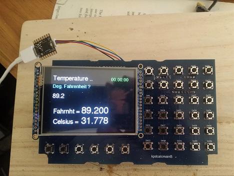 PROGRAM tempmod DOUBLE fahr, celsius FORMAT (F9.3,/) CALL descs ( ) READ (3,*) fahr celsius = 5.0 * ( fahr - 32.0 ) / 9.0 WRITE (4,0) fahr, celsius END SUBROUTINE descs ( ) QZFTXT QZFA "Temperature .." QZFTXT QZFB "Deg. Fahrenheit ?" QZFTXT QZFE "Fahrnht =" QZFTXT QZFF "Celsius =" QZFSEQ QZFF " MN" RETURN END The "QZ" statements just populate/sequence the display fields and data. |
||||
| zeitfest Guru Joined: 31/07/2019 Location: AustraliaPosts: 683 |
Now running OK on a routine Pico 2, with SD card hanging ten  . .I think I will try to make a small module utility board that adds a 3231 rtc, the sd socket and a 1115 A/D, any suggestions eg for standard pin connections welcome. Have to tone down the tactile switches a bit ! They are a bit beady to use after a while. Trialing squishy silicone pads on top. 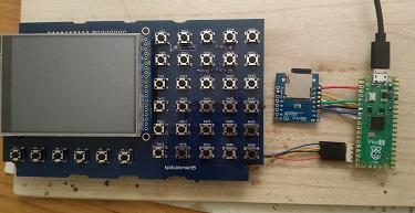 |
||||
| The Back Shed's forum code is written, and hosted, in Australia. | © JAQ Software 2026 |
