|

|
Forum Index : Microcontroller and PC projects : mcp23017 port expander again
| Author | Message | ||||
| lizby Guru Joined: 17/05/2016 Location: United StatesPosts: 3150 |
For output: ' i2c_pcf8574.bas Dim integer k1=&b10101010,k2=&b01010101 SetPin 6,7,i2c I2C open 100,100 Do I2C write &h20,0,1,k1: I2C write &h12,0,1,k2: Pause 500 I2C write &h20,0,1,k2: I2C write &h21,0,1,k1: Pause 500 If Inkey$="x" Then Exit Loop I2C write &h20,0,1,255: I2C write &h21,0,1,255 ' turn off Note that it's "inverted"--0 turns on and 1 turns off. PicoMite, Armmite F4, SensorKits, MMBasic Hardware, Games, etc. on fruitoftheshed |
||||
| lizby Guru Joined: 17/05/2016 Location: United StatesPosts: 3150 |
Did you try this? Same port definitions as for writing. Then, at some point (for port B) I2C WRITE MCP23017,0,2,GPUPB,&h3f ' set weak pullups on all except bits 6&7 then when you read: I2C WRITE MCP23017,0,1,GPIOB ' set the register to read I2C READ MCP23017,0,1,inputs ' read the B port the integer "inputs" will contain the 8 bits of values. PicoMite, Armmite F4, SensorKits, MMBasic Hardware, Games, etc. on fruitoftheshed |
||||
| lizby Guru Joined: 17/05/2016 Location: United StatesPosts: 3150 |
The Raspberry PI RP2040-Zero linked to is not an rpizero. It's just a version of the Pico we've been using--not a Pico PCB, but a PCB with the same RP2040 microprocessor. Here's a thread on using the Pico as an I/O expander: Pico as serial or i2c client In one version, you set up the second, client, Pico with serial console, and then just send MMBasic commands as if you were typing at the console. The tricky part is decoding what you get back if you want to handle inputs. (But you're very close with the MCP23017--try again and post your entire code here if it doesn't work.) PicoMite, Armmite F4, SensorKits, MMBasic Hardware, Games, etc. on fruitoftheshed |
||||
| Turbo46 Guru Joined: 24/12/2017 Location: AustraliaPosts: 1611 |
Bill Keep safe. Live long and prosper. |
||||
| phil99 Guru Joined: 11/02/2018 Location: AustraliaPosts: 2135 |
If you want a RP2040 as an expander that is cheaper than the RP2040-Zero and has more pins and flash, search AliExpress for "Purple RP2040 USB-C 16MB". One example https://www.aliexpress.com/item/1005003199099382.html From the group on the right select the purple one. Edited 2023-12-01 16:47 by phil99 |
||||
| Mixtel90 Guru Joined: 05/10/2019 Location: United KingdomPosts: 6798 |
Be very careful with the purple one. It's nowhere near pin compatible with the Pico. The black one is much better. That one is, I think, the YD-RP2040. More or less the same as a Pico but max CPU speed under MMBasic is 252MHz from my experiments. The power pins are a bit different but you can't back-feed into the USB. You might find the pinout of the purple board to be better as a remote IO, but there are less GND connections so you may have to be careful with the IO speed and board layout. Mick Zilog Inside! nascom.info for Nascom & Gemini Preliminary MMBasic docs & my PCB designs |
||||
| phil99 Guru Joined: 11/02/2018 Location: AustraliaPosts: 2135 |
Quite right, but I mentioned it as an alternative to the RP2040-Zero as an expander, that is also "nowhere near pin compatible". Mine runs happily at 378MHz and so far no issues with I/O speed. To minimise the problems caused by so few ground pins one is dedicated to the ADC pins. |
||||
| Mixtel90 Guru Joined: 05/10/2019 Location: United KingdomPosts: 6798 |
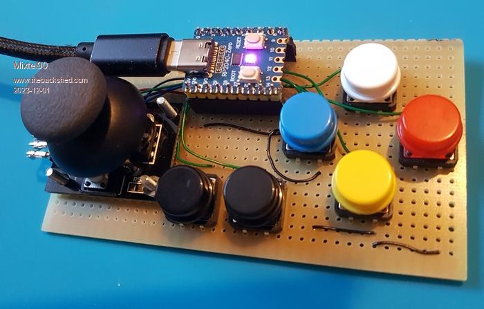
 Here's my current prototype controller using the RP2040-Zero. I needed a small PCB area device and I hadn't got any Micromites! It's in address config mode here (magenta light). You press a colour key to set the address to one of 4 different I2c addresses. Communication is via 5 registers (at the moment). R0 - config R1 - 4 direction bits for the joystick and 4 direction bits for the colour buttons R2 - the two black buttons and the joystick switch. Intending to add two more buttons and two trigger buttons on the final build. R3 - Joystick X-axis analogue value 0-255 (approx.) R4 - Joystick Y-axis analogue value 0-255 (approx.) Two bits of R0 tell the controller how many registers to send on a Read command: 00 - just R1 01 - R1 & R2 10 - R2, R3 & R4 11 = R1, R2, R3 & R4 Reducing the number of messages increases the read speed, obviously. :) The LED normally indicates the channel colour that it's using. This is saved using VAR SAVE so it returns to the same channel next time it's used. I've not done the I2C comms on this yet, but I did on an earlier breadboard prototype so I know it can be done reasonably easily. Edited 2023-12-01 23:07 by Mixtel90 Mick Zilog Inside! nascom.info for Nascom & Gemini Preliminary MMBasic docs & my PCB designs |
||||
| lizby Guru Joined: 17/05/2016 Location: United StatesPosts: 3150 |
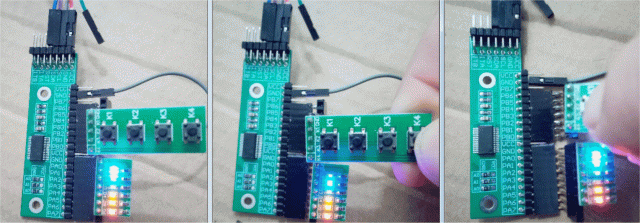
Here is working code, working hardware:  ' MCP23017_IO.bas Const mcp23017 = &h20 ' A2, A1, A0, R/W all connected to 0V Const i2caddr=mcp23017 Const IODIRA = &h00 ' Port A IO Direction register DEFAULT = I/P Const IODIRB = &h01 ' Port B IO Direction register DEFAULT = I/P Const IOCON = &h0A ' IO Expander config register--address &h0B accesses same register Const GPIOA = &h12 ' Port A General purpose register Const GPIOB = &h13 ' Port B General Purpose register Const OLATA = &h14 ' Port A latch register Const OLATB = &h15 ' Port B latch register Const GPUPB = &h0D ' Port B pull-up register 'I2C2 open 100, 1000 I2C2 WRITE MCP23017,0,2,IODIRA,0 ' set direction to output I2C2 WRITE MCP23017,0,2,IODIRB,255 ' set direction to input I2C2 WRITE MCP23017,0,2,GPUPB,&hff ' set weak pullups on all bits mcp17 Pause 1000 Do mcp17in Loop Sub mcp17 Print "write to mcp23017" For i = 1 To 6 I2C2 Write MCP23017,0,2,OLATA,&b10101010 ' ' I2C2 Write MCP23017,0,2,OLATB,&b01010101 ' Pause 1000 I2C2 Write MCP23017,0,2,OLATA,&b01010101 ' ' I2C2 Write MCP23017,0,2,OLATB,&b10101010 ' Pause 1000 Next i I2C2 Write MCP23017,0,2,OLATA,0 ' turn all off 'I2C2 Write MCP23017,0,2,OLATB,0 ' turn all off Pause 1000 End Sub Sub mcp17in I2C2 write MCP23017,0,1,GPIOB I2C2 read MCP23017,0,1,portabits Text 0,20,Bin$(portabits,8) Print Bin$(portabits,8) I2C2 Write MCP23017,0,2,OLATA,portabits Pause 3000 End Sub Edited 2023-12-02 02:51 by lizby PicoMite, Armmite F4, SensorKits, MMBasic Hardware, Games, etc. on fruitoftheshed |
||||
| PhenixRising Guru Joined: 07/11/2023 Location: United KingdomPosts: 865 |
Oh, absolutely...it's a no-brainer when you think that you can command the outs to be PWM'd, etc. And for those smart enough (not me) to use the PIO....unlimited possibilities. |
||||
| stanleyella Guru Joined: 25/06/2022 Location: United KingdomPosts: 2129 |
Happy days, input works and all b0 to b7 work as input if grounded. They are normally high from the weak pull up but it seems you can invert them so grounding makes them high. Interrupt on pin change next :) credit to lizby and andy but all help was appreciated, thanks. OPTION EXPLICIT OPTION DEFAULT NONE dim integer portabits const mcp23017 = &h20 ' A2, A1, A0, R/W all connected to 0V Const i2caddr=mcp23017 const IODIRA = &h00 ' Port A IO Direction register DEFAULT = I/P const IODIRB = &h01 ' Port B IO Direction register DEFAULT = I/P const IOCON = &h0A ' IO Expander config register - address &h0B accesses same register const GPIOA = &h12 ' Port A General purpose register const GPIOB = &h13 ' Port B General Purpose register const OLATA = &h14 ' Port A latch register const OLATB = &h15 ' Port B latch register const GPUPA = &h0C ' Port C pull-up register const GPUPB = &h0D ' Port B pull-up register ' I2C WRITE MCP23017,0,2,IODIRA,255 ' set direction to input I2C WRITE MCP23017,0,2,IODIRB,255 ' set direction to input I2C WRITE MCP23017,0,2,GPUPB,&hff ' set weak pullups on all ' Font 2 CLS ' Do 'then when you read: I2C WRITE MCP23017,0,1,GPIOB ' set the register to read I2C READ MCP23017,0,1,portabits ' read the B port text 0,20,bin$(portabits,8) Pause 100 Loop maybe I was lucky that chips I got read all ports as inputs. ps works at full over clock. Edited 2023-12-02 11:08 by stanleyella |
||||
| Mixtel90 Guru Joined: 05/10/2019 Location: United KingdomPosts: 6798 |
I think the main problems with bit 7 arise when you are using pulse train or square wave inputs. I've not done that much research on it, but others have seen missing pulses on that bit whereas they are perfect on the other inputs. Low speed buttons etc. might be ok, but if you do see problems at least you'll have the comfort of knowing that it doesn't have to be your wiring. :) Mick Zilog Inside! nascom.info for Nascom & Gemini Preliminary MMBasic docs & my PCB designs |
||||