|

|
Forum Index : Microcontroller and PC projects : [PicoMite] count input on rising edge PROBLEM, no it's not me!
| Author | Message | ||||
| Amnesie Guru Joined: 30/06/2020 Location: GermanyPosts: 396 |
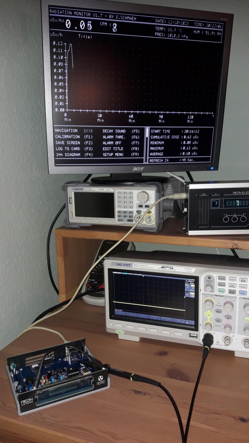
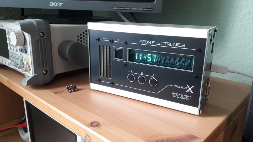
Mick, I think my whole attempt to solve this with just one additional transistor is bad. Good for me, that I don't need the onboard buzzer, but use the speaker i've built into my all-in-one "Project X" unit you can see here above the scope.   Do you think a reversed diode will solve this? I theory it should. Vcc is 5 Volts. But as you can see, now my whole project is running. The "Project X" unit with the picoMite and the additional Geiger Counter + way more complex Geiger software on the VGA monitor. I am so glad for this community and MMBASIC at all. Greetings Daniel Edited 2023-10-13 04:34 by Amnesie |
||||
| Mixtel90 Guru Joined: 05/10/2019 Location: United KingdomPosts: 6798 |
Well, it looks a bit like a big back emf spike. The transistor is seeing a narrow pulse and the buzzer is inductive. There must be a collapsing field at some point. It might be worth a try. Mick Zilog Inside! nascom.info for Nascom & Gemini Preliminary MMBasic docs & my PCB designs |
||||
| LouisG Senior Member Joined: 19/03/2016 Location: AustraliaPosts: 124 |
That's interesting! Matherp said earlier that Setting 2 of the CIN command applies a pullup resistance to the input. Is this really the case? I can't find anything in the manual (except for DIN). I presume then that a pulldown would be applied for Setting 1. Do FIN and PIN commands automatically apply pulldowns? I'm asking because until now I have been adding external pulldown resistors for CIN and FIN for fear of leaving an input floating. |
||||
| Mixtel90 Guru Joined: 05/10/2019 Location: United KingdomPosts: 6798 |
It's always a good idea to use external resistors if the signal lines are of any length and you have PCB space as it reduces noise. The internal pullup/pulldown resistors have a very high value. Mick Zilog Inside! nascom.info for Nascom & Gemini Preliminary MMBasic docs & my PCB designs |
||||