
|

|
Forum Index : Microcontroller and PC projects : High Spec RP2040 Game PCB
| Author | Message | ||||
| thwill Guru Joined: 16/09/2019 Location: United KingdomPosts: 4042 |
I suppose I should stop sulking  How is this possible given for compatibility with the Game*Mite you needed 8 specific GPIO pins free, were some of those not required by the standard PicoMite parallel display allocation? Is there a manual/analog or a digital volume control? Surely the problem with the latter is that each program has to be adapted to deal with it. The former just works. How big is it, it looks smaller than a Game*Mite with a less ergonomic "controller" ? Best wishes, Tom Game*Mite, CMM2 Welcome Tape, Creaky old text adventures |
||||
| matherp Guru Joined: 11/12/2012 Location: United KingdomPosts: 9122 |
Being in charge of the firmware allows a little flexibility to be added to pin allocation  OPTION LCDPANEL parallel_display,orientation [,backlightpin] [,DC pin] So: the parallel display will always use 0-7 for the signal pins but the 4 control pins can be placed anywhere DC,WR,RD,RESET starting at "DC_in" and, of course that defaults to the previous mandatory configuration if omitted. Now manual - same pot as you are using but wired for stereo 100x100 If you want to supply them then once I have checked the design and published the gerbers then please do - I think the price is very good for a fully built unit. I don't and won't ever sell things - much too much hassle. Edited 2023-10-21 19:28 by matherp |
||||
| thwill Guru Joined: 16/09/2019 Location: United KingdomPosts: 4042 |
Hi Peter, The schematic still shows an i2c bus expander but the connections from PicoMite to switches just seen to pass straight through it on a 1:1 basis ? Thanks Peter, but it's one thing to package up a few components and sell at close to cost to a few forgiving hobbyists but something entirely different to have to invest 125+ in stock and sell a more "complete" device. I suspect there are also regulations on sale of electronics devices, tax concerns and conflicts with my contract of employment that couldn't just be glossed over. If your device (as impressive as it is, and as jealous as I am of your skills) is to have a future it will be with the existing 'mite vendors, and of those it looks like only @Grogster is still active  . .Best wishes, Tom Game*Mite, CMM2 Welcome Tape, Creaky old text adventures |
||||
| matherp Guru Joined: 11/12/2012 Location: United KingdomPosts: 9122 |
Just a label I left on the schematic by mistake - the chip has gone - the "expander" is just a header like on your board. The design is only possible smd because it needs the extra 3 pins on the RP2040 that are used on the Pico |
||||
| lizby Guru Joined: 17/05/2016 Location: United StatesPosts: 3150 |
Well, if there are 4 others in Canada or the U.S. interested for cost plus shipping, I'll bite if Peter confirms the gerbers are now ready for ordering. Caveats: for Canadians, the boards would have to get to me by November 15 for me to be able to ship them before I snowbird south; and for Americans, I wouldn't be able to ship before Nov. 21 at the earliest. Even with slow boat shipping they should arrive in time if ordered very soon. The price for me for shipping a standard set of 5 bare 100mm x 100mm PCBs is $3.44 for slow boat, and $50+ for expedited. (By the way, I think Tom's Game*Mite is very likely to be able to play the Petscii Robots game now under development, and I'm not at all sure what will come along which will require the speed of the parallel ILI9341.) PicoMite, Armmite F4, SensorKits, MMBasic Hardware, Games, etc. on fruitoftheshed |
||||
| thwill Guru Joined: 16/09/2019 Location: United KingdomPosts: 4042 |
I also have this suspicion, but nevertheless have the parts for a thru-hole Game2Mite prototype in the post that will use the standard Pico plus a shift-register as input expander (and thus not be 100% Game*Mite compatible, but I know how to deal with that). This may well be just something I play with as a private project, but we'll see. Peter, regarding your board I'll offer these thoughts based on experience with the Game*Mite ... even though I'm still a bit "put out" that it might stop @bigmik and I getting back some of our development costs  : :1. Unless you've differed deliberately consider a direct copy of the Game*Mite's control area as it is ergonomically tried and tested, if nothing else just shift the buttons up a bit as it looks like they are too close to the bottom edge for comfort. 2. Consider how it might be possible via the 10-pin header and mounting holes to create a daughter board version of the control area (as an alternative option) that would then sit at the same level as the LCD module. You'd need to add at least one more pin to the header to handle RESET and you need to be careful of horizontal clearance between the LCD and daughter board. I believe that such a design (LCD and controls at same level) will be easier for someone to encase. 3. I suspect people would want to mount the battery and speakers underneath, rather than via the terminal blocks on top, check that is catered for. 4. Assuming it will make very little difference to the cost consider adding a "push-push" type uSD card (on the same pins as the LCD one), a full sized one sticking out of the LCD is liable to be accidentally snagged. Less of a problem for your design of course because of the bigger flash. I'm not going to claim special ownership of the Game*Mite name and considering the compatibility I don't mind you using it, perhaps "Game*Mite+" or "Game*Mite P" or "Game*Mite X" ... I'd quite like to reserve "Game2Mite" for myself if you don't object. YMMV. Peter, If you would like a complimentary Game*Mite kit (and you'll actually build it) then you only have to say. I didn't offer you one because you've previously expressed that you "have no interest in games"  . .Best wishes, Tom Edited 2023-10-22 00:52 by thwill Game*Mite, CMM2 Welcome Tape, Creaky old text adventures |
||||
| matherp Guru Joined: 11/12/2012 Location: United KingdomPosts: 9122 |
Tom Prior to the recent changes and implementation of CPU2 updates there is no question in my mind that an SPI screen would have been too slow for something like Petscii. The changes I've made make it more possible but there are compromises like blocking/crashing with sdcard access. If you consider a second SPI version I would definitely recommend to put the sdcard on different pins to the display. I'm sorry if you think I've trodden on your and Mick's toes. I do stuff just for the fun of it and to push things and my knowledge further (like having all the power circuitry and amp on board rather than using modules) and always then make the designs available free of charge and never sell anything. Having done the rp2040/flash circuitry on the VGA boards this is now a "module" I can incorporate on any design and know it will work with a defined set of components that I know JLC normally have in stock. I can now add a full battery supply module and amp to that. I hear what you say about the daughter board. I'm thinking about one for the speakers. Thanks for the offer on the PCB but it would only be used as another development board and I can mimic it reasonably enough for testing. One area where we obviously differ is that I now see no real use for through hole designs. The costs of having stuff made at JLC even in small quantities are so low that I don't think you can justify the time to solder up even a simple board like the GameMite. It also saves all the hassle of buying in components from multiple sources. If the design is right the boards arrive and work first time. |
||||
| thwill Guru Joined: 16/09/2019 Location: United KingdomPosts: 4042 |
Hi Peter, We will have to agree to differ. I've been watching progress avidly and I'm pretty certain it would still have worked prior to your impressive improvements; though I will admit it might have needed a sprinkle of CSUB magic in the main AI processing loop. I'd consider it. Probably as an option because for some potential applications of the Game*Mite the free GPIO is more important. Personally I see not being able to access the SD card at the same time as updating the display in the background to be an acceptable limitation. You can't have everything you want from a $5 micro-controller plus a few discrete components. I probably composed 2000 lines of response to that in my head, but they are more suitable for a conversation in the pub than on the internet. You didn't do anything wrong, I practically invited others to make their own versions (I just didn't think it would be you given previously expressed disdain for games). You've just made it more difficult for me, there was (possibly still is) going to be a video on the Game*Mite that I would have shared beyond TBS, but now I find myself in the position of promoting a device for which there is an alternative (IMO not in all ways) superior device which nobody is going to supply  . Anyway, water under the bridge and I should be less petulant about it. . Anyway, water under the bridge and I should be less petulant about it.It was more so that you might be able to see the ergonomics I was talking about. Many reasons for my preference for thru-hole for the Game*Mite: 1. That's my level of expertise; Mick could have done better, but he respected my wish that he design a PCB that I might have been able to design for myself given another 12 months of osmosis from TBS. 2. Some people like putting together kits; we're the people who buy Airfix models and Lego rather than Diecast and other pre-built collectables. 3. Though relatively young by TBS standards I'm still of an age that I'd rather not be spending my hobby time squinting through a microscope or crawling around on my hands and knees looking for a component 1/8th the size of a grain of rice. 4. Some people like buying odds and ends from eBay and AliExpress and waiting for the little packages drop through the door. 5. Thru-hole is more hackable. It's easy for a hobbyist to take the existing Game*Mite and add stereo sound, replace the controller configuration, use three AAA batteries instead of the LiPo or hack it to use as @Volhout's logic analyser. 6. Thru-hole components are "what electronics looks like" in the part of my brain that is still 2-4 years old and would run around the house with a "sue-dadder" to his parent's horror (in case he fall and skewer himself) and who blew the electrics by rewiring an electric razor that he had found in a box of discarded broken electronics. YMMV, Tom Edited 2023-10-22 09:38 by thwill Game*Mite, CMM2 Welcome Tape, Creaky old text adventures |
||||
| Mixtel90 Guru Joined: 05/10/2019 Location: United KingdomPosts: 6798 |
TBH I like to have both options open. On one hand there's the kit, which I love (I've always loved building electronic kits!). Even if the final spec is lower it's the one I would choose first. On the other hand there is a SMD alternative, which is great if you want a Game*Mite but aren't into the delights of solder fumes and singed fingertips. Having them both in the same form factor - and still being able to see the "bits" is great. My grandson recently begged a faulty game-thingy from my wife so that he can take it to pieces to see what's inside. I think seeing my Game*Mite might be having an influence on him. :) Peter, I agree with Tom on the thumb button positions. It would be nice if they were in similar positions. Perhaps no need for a PCB, a sketch would be close enough. It would give a closer look to the "family". Incidentally, from early experiments I think a sub-pcb for the "Chinese" buttons would be on 5mm spacers. I've still to confirm this. My overall experiment is to lever the whole system into a Hammond case for those who don't like their electronics to serve dual purpose as dust magnets. :) It's too early to say how well this might go. I don't see 3D printed cases as a serious option. Mick Zilog Inside! nascom.info for Nascom & Gemini Preliminary MMBasic docs & my PCB designs |
||||
| thwill Guru Joined: 16/09/2019 Location: United KingdomPosts: 4042 |
Just an observation that if I were designing this to be sold by myself then I would probably intend to supply it with the display module because they are more difficult to source than the SPI version. I wouldn't be keen on providing a LiPo though so I would probably have the charging circuit isolated by jumpers (disconnected by default) and instead provide a 3xAAA battery box. YMMV, Tom Game*Mite, CMM2 Welcome Tape, Creaky old text adventures |
||||
| Mixtel90 Guru Joined: 05/10/2019 Location: United KingdomPosts: 6798 |
Having investigated further, I can't fit a normal AAA holder into the case. Mind you, you probably wouldn't be wanting to keep opening the case to change the batteries anyway. The case is rather cramped. Even restricting the display to 2.8" hasn't helped much. The board has to be packed up to almost half the depth of the case too. I might not bother as I doubt if demand would be high. Mick Zilog Inside! nascom.info for Nascom & Gemini Preliminary MMBasic docs & my PCB designs |
||||
| matherp Guru Joined: 11/12/2012 Location: United KingdomPosts: 9122 |
I've taken on board various comments and the result is 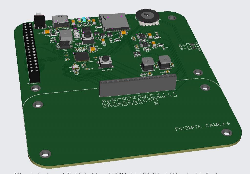 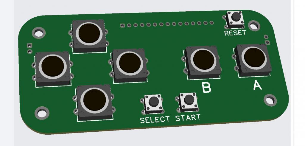 Schematic 4f2bc1ad-a3a1-4e76-a19d-0b97ed4f405b.pdf Changes are: All user switches now on a daughter board together with the terminals for the speakers 10k pot added to the charge circuit micro-SD slot added Volume control, switch, USB-C, LEDs, and sdcard all on top edge for easy access in a "box" Unfortunately the main board is now 110mmx100mm which has a small impact on price (GBP6.77 vs GBP1.65 for 5) but there simply isn't room for a decent switch layout below the 3.2" 8-bit parallel ILI9341. Edited 2023-10-29 01:01 by matherp |
||||
Quazee137 Guru Joined: 07/08/2016 Location: United StatesPosts: 571 |
Thanks Peter I have had request for small single box water-tower controllers and this fits nicely instead of the buttons I see using the header right angled on the back side going to a board with the few needed relays, ADS1115, RS232 and flash with board setup hardware information. I can use this as the base and only need to build the custom bit on the plugin board. With this I can use a few pictures then animate over the top to show system running and setup/calibrate with added audio. I have 3 of Grogsters LVT boards out being field tested using 10'displays. The main comment is not portable enough for fast setup. One other thought is a bread board in place of buttons for educational use. Lesson code and images on SD card. This is FUN stuff Quazee137 |
||||
| matherp Guru Joined: 11/12/2012 Location: United KingdomPosts: 9122 |
Would be great if there are other uses  Here's an idea. Why not make the switch PCB a bezel for the screen? 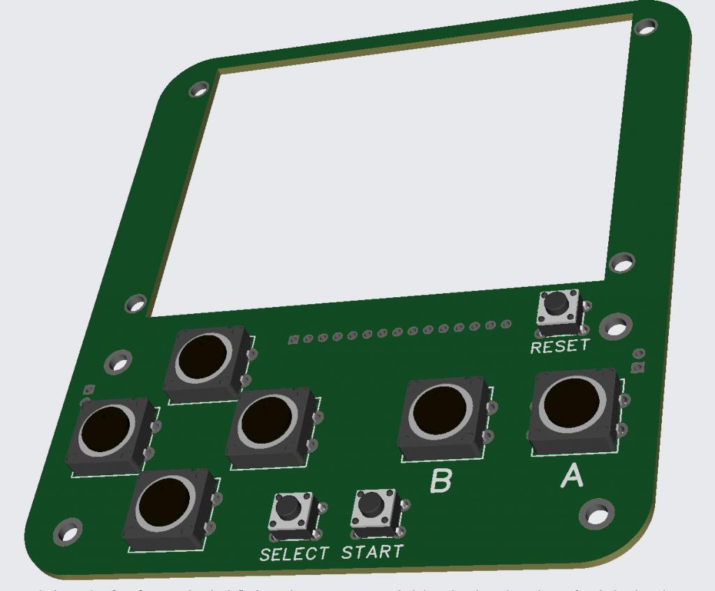 |
||||
| Mixtel90 Guru Joined: 05/10/2019 Location: United KingdomPosts: 6798 |
Because, if you use the Chinese buttons that Tom used, the buttons may be too high. The top clips onto the switch base and has a lip round it, intended to come up against the inside of the top plate. I discovered that putting the button board on 5mm spacers brought the lip up to about the same level as the front surface of the display. Of course, you can't fit a SIP connector in the 5mm gap. Mick Zilog Inside! nascom.info for Nascom & Gemini Preliminary MMBasic docs & my PCB designs |
||||
| thwill Guru Joined: 16/09/2019 Location: United KingdomPosts: 4042 |
I like the bezel (I had/have similar ideas for the Game*Mite), but like Mick says you would need to make sure you used SMD buttons on the "daughter-board". I was going to suggest that you could get the main PCB back to 100x100mm by having the daughter-board overhang the main PCB by 10mm, though that isn't compatible with using it as a bezel, unless the bezel is then "outsize". Looking good, Tom Game*Mite, CMM2 Welcome Tape, Creaky old text adventures |
||||
| matherp Guru Joined: 11/12/2012 Location: United KingdomPosts: 9122 |
Courtesy of Mick's PCB design 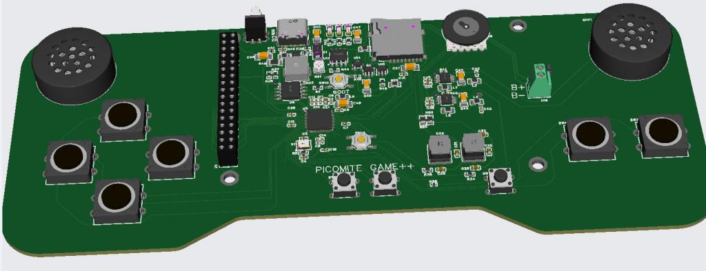 LCD will mount direct without a connector and a top bezel cutout will hide the battery with the display, speakers and switches poking through Edited 2023-10-29 07:50 by matherp |
||||
| Mixtel90 Guru Joined: 05/10/2019 Location: United KingdomPosts: 6798 |
I wonder why that appeals to me? ;) Did you need to scale it up for the 3.2" display? I didn't design it round that one. Mick Zilog Inside! nascom.info for Nascom & Gemini Preliminary MMBasic docs & my PCB designs |
||||
| matherp Guru Joined: 11/12/2012 Location: United KingdomPosts: 9122 |
Here's the final version. Because the display will mount direct to the board the level of the switches and screen should be good. I'll get a couple made and then release the gerbers. When they arrive I'll also do a 3D print box design 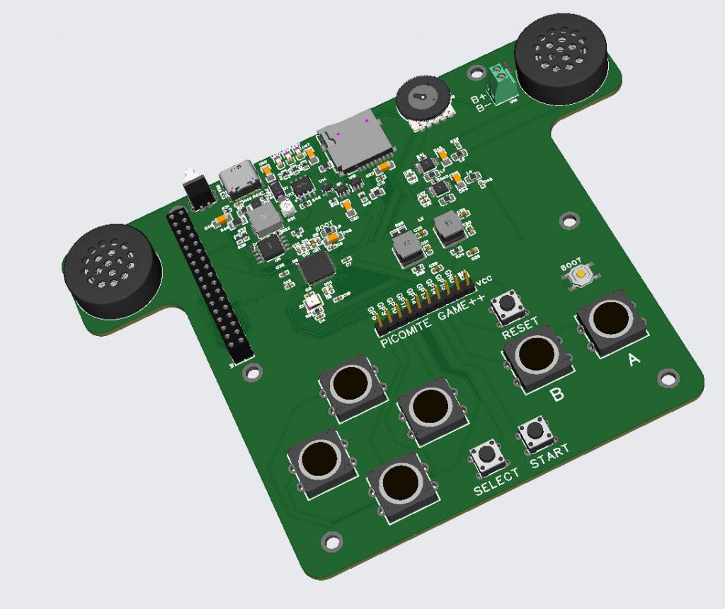 4683d882-0388-4721-a757-f82ebdc0fd66.pdf All parts are in stock at JLC but it probably makes sense to fit the switches yourself so you can chose the exact type and the two headers should be omitted (included for clarity) Cost for 5 boards with all components as shown GBP98.4 plus shipping and any relevant taxes. Cost with all through hole components omitted GBP74.88 Edited 2023-10-29 22:39 by matherp |
||||
Quazee137 Guru Joined: 07/08/2016 Location: United StatesPosts: 571 |
Looks like C5 is missing in the current PDF. Will there be gerbers for 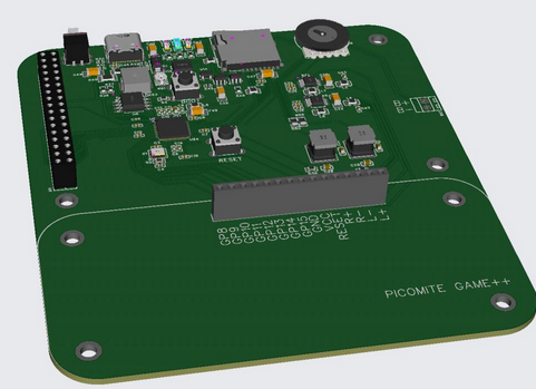 Quazee137 |
||||