|

|
Forum Index : Microcontroller and PC projects : Armmite F4 LCD interface PCB
| Author | Message | ||||
| Mixtel90 Guru Joined: 05/10/2019 Location: United KingdomPosts: 6798 |
Nope, unfortunately I haven't got one of those displays (and I can't afford one at the moment). The general form of construction is similar to the original Hydra so those instructions are a good guide. The main differences are that the display is wired differently (obviously!), the PCB over the Armmite is narrower to make it easier to read the pin text and there are a few more components squeezed in. There is one point - on the revised board there is an optional Piezo sounder. This has to be an *active* type and could also be a 5V active magnetic type. Passive devices won't work. I'll try to get round to some circuit diagrams, but they would be so rudimentary really. Mick Zilog Inside! nascom.info for Nascom & Gemini Preliminary MMBasic docs & my PCB designs |
||||
| lizby Guru Joined: 17/05/2016 Location: United StatesPosts: 3150 |
It's a sweet display. I have several working on the F4 using a minimalist adapter. I expect JLC to say they're shipping it any day now. Then about 10 days for delivery. PicoMite, Armmite F4, SensorKits, MMBasic Hardware, Games, etc. on fruitoftheshed |
||||
| Mixtel90 Guru Joined: 05/10/2019 Location: United KingdomPosts: 6798 |
They usually take 2-4 days to manufacture. 2 days in green, 4 in a colour to match your curtains.. :) I don't know if these will be a little slower, being 4 layers and a funny shape. Edited 2023-09-23 18:16 by Mixtel90 Mick Zilog Inside! nascom.info for Nascom & Gemini Preliminary MMBasic docs & my PCB designs |
||||
| Mixtel90 Guru Joined: 05/10/2019 Location: United KingdomPosts: 6798 |
This is the combined circuit diagram for the various versions of the Hydra. Hydra II is still work in progress. I'm considering going back to 2-layer boards as I've discovered that it's possible to do, if a little messy. Hydra circuit diagrams.pdf Mick Zilog Inside! nascom.info for Nascom & Gemini Preliminary MMBasic docs & my PCB designs |
||||
| okwatts Regular Member Joined: 27/09/2022 Location: CanadaPosts: 59 |
Hey Mick (&lizby) I soldered just the connectors for the display to the Hydra40-80 (revised gerbers) and shorted the links for the "old" dev board. I've noticed something unusual (at least to my understanding) that when I plug in the ips display the USB port disappears. I can connect through the serial console and then turn it off remove the display and I'm back to using the USB. Is there an explanation since I have not brought power to the Hydra from the dev board. Is that lack enough to explain this? |
||||
| Mixtel90 Guru Joined: 05/10/2019 Location: United KingdomPosts: 6798 |
Good question. The system is designed to normally take power from the USB. It passes through the 0R link on the F4 , feeds the on-board regulator to power the F4 and also through an external Schottky diode feed the 5V rail. It then feeds the display directly and a voltage regulator to give a second 3V3 rail. A link is provided to power the F4 from the Hydra's regulator, but if you are powering from the USB don't fit it. That's only for powering the Hydra from 5V. You can't normally use the F4 like that without removing R5 or replacing it with a Schottky diode. Another possibility may be that the backlight current is sinking the USB's 5V supply. Any help? If the F4 is powered but the Hydra (and hence the display) isn't then all bets are off. The data pins of the display could be holding pins down as it's not initialised. Edited 2023-10-25 08:08 by Mixtel90 Mick Zilog Inside! nascom.info for Nascom & Gemini Preliminary MMBasic docs & my PCB designs |
||||
| okwatts Regular Member Joined: 27/09/2022 Location: CanadaPosts: 59 |
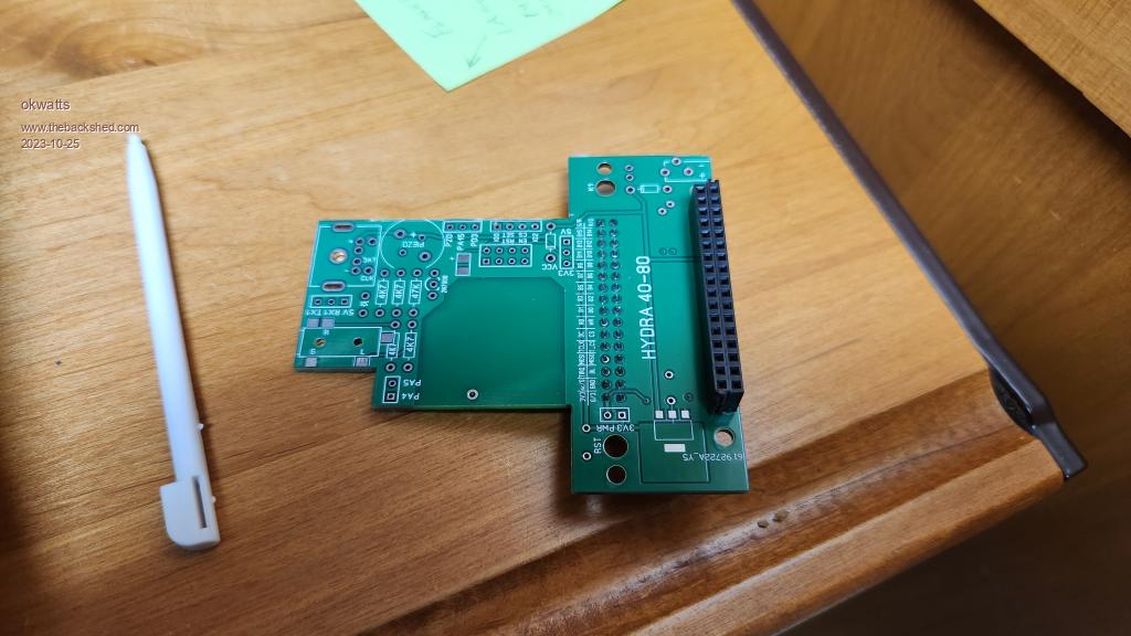
I had a look and it appears there are 2 issues. the first is that without the power input to the hydra40-80 there is no power to the IPS display since the pnly power from the F4 board is 3.3v at the display connector. The other larger issue is I believe the connector for the IPS on the HYdra40-80 is not flipped to match the mounting of the display on the top side. I enclose a picture of my board as built.  |
||||
| Mixtel90 Guru Joined: 05/10/2019 Location: United KingdomPosts: 6798 |
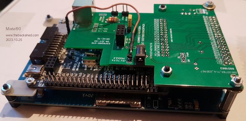
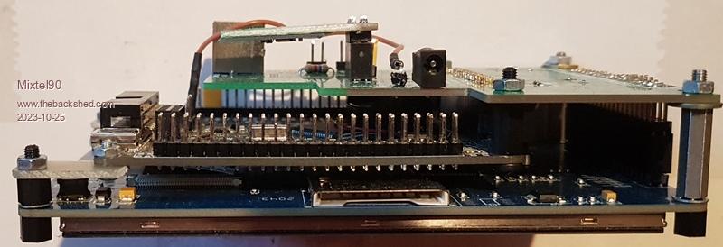
Ah, you've assembled it wrong. :( The display connector goes on the bottom of the board in your photo, so both connectors are on the same side. This sounds weird until you look at he final assembly. These pics are of the prototype. As I said, I haven't got an IPS display or a Hydra 40-80 board. It's the same idea though. The shape of the Hydra board lets you get to the pins of the Armmite F4.   The component silkscreen goes to the top of the assembly when the display is lying face down on the table, as shown in your pic. ----------- 5V from the Armmite F4 is best picked up from the serial port connector 5V pin via a link wire to the serial port on the Hydra. (Innermost pin, next to the diode, between the PS/2 and audio connectors). With this connection in the whole system is powered from USB. This is the brown Dupont wire shown in the pics of the prototype. ------------- Spacers used in the above assembly are 5mm (6 off) for the end and front, 11mm (2 off) for the F4-Hydra join and 18/19mm (2 off) for the Hydra-display join. I used 18mm for the latter but had to pad it a little with washers to get the F4 parallel to the display. . Edited 2023-10-25 17:34 by Mixtel90 Mick Zilog Inside! nascom.info for Nascom & Gemini Preliminary MMBasic docs & my PCB designs |
||||
| okwatts Regular Member Joined: 27/09/2022 Location: CanadaPosts: 59 |
Okay makes sense when you see it,although it is "backwards" to the way the 3.2inch ILI9341 parallel display and lizby's adapter board are arranged. I should have read the instructions for your original Hydra more carefully. Typically for me just proceeding with what I thought made sense! Fortunately I have 4 more boards left and now I need to source the long tail female connectors to attach to the display. Thanks for the clarification. |
||||
| Mixtel90 Guru Joined: 05/10/2019 Location: United KingdomPosts: 6798 |
I really should have included a photo or drawing showing the assembly in more detail. :( If you have solder braid and liquid flux or, even better, a hot air gun, that connector can be removed. This I know 'cos I've done it. :) You do have to be careful though as individual pins can sometimes pull out of the moulding. Not a great problem as they can be pushed back afterwards. The reason it's backward in comparison to the usual backpacks is because the video connector of the Armmite F4 faces in the same direction as the IO pins. If you want access to them you have a problem unless you are happy with having everything spread across the desk. It doesn't work if you want to install the bits in a housing unless you link the display using ribbon cable. I fancied something that worked mechanically like the usual backpacks but used the F4. Mick Zilog Inside! nascom.info for Nascom & Gemini Preliminary MMBasic docs & my PCB designs |
||||
| PhilP Newbie Joined: 25/01/2017 Location: United KingdomPosts: 31 |
Mick - I am glad this topic was brought up as I started assembling your kit before my STM32 board arrived. I soldered in the large connector and then had doubts that it was on the right side especially as the other connected was marked on the same side which seemed odd. Yesterday my STM board arrived and I could see all was OK and I didn't have to try to a lot of desoldering. I am trying to programme the board now and eventually downloaded the programmer (382Mbs) and I am trying to find the latest Armmite MMB. I am following Peter's guide from Fruit of the Shed which talks about using a .HEX file. In the thread the latest version in the 'Armmite F4: programming the firmware' thread is a BIN file posted on 09:24am 29 Nov 2019 by Peter. Is this the latest and presumably it is an older version of MMB. I can understand that it will not be possible to maintain and update the multiple versions of MMB for all platforms. Phil |
||||
| Mixtel90 Guru Joined: 05/10/2019 Location: United KingdomPosts: 6798 |
Watch this thread for the current version. Edited 2023-10-26 20:51 by Mixtel90 Mick Zilog Inside! nascom.info for Nascom & Gemini Preliminary MMBasic docs & my PCB designs |
||||
| phil99 Guru Joined: 11/02/2018 Location: AustraliaPosts: 2135 |
@PhilP I think this is a later version https://www.thebackshed.com/forum/uploads/disco4now/2023-08-27_201409_ArmmiteF4_5.07.02betas.zip Page 3 of this thread Edited 2023-10-26 21:46 by phil99 |
||||
| okwatts Regular Member Joined: 27/09/2022 Location: CanadaPosts: 59 |
I'm still waiting for some long pin female connectors for the HYdra 40-80 and have been gathering other parts (SMD bits etc.) I a question about the barrel connector for the power input as it is a size I have not encountered. I have a number of power connectors but they are all larger in the pin spacings. Do you have a part number I can refer to Digikey is my preferred supplier but any reference would be helpful. Thanks |
||||
| Mixtel90 Guru Joined: 05/10/2019 Location: United KingdomPosts: 6798 |
I originally got the r connectors from an ebay seller in China. However, Switch Electronics in the UK have them in their ebay shop. They are readily available on AliExpress too. Link Many people won't need this connector as they';; be powering the system from USB. Note that the pads are on the same centres as miniature screw terminal blocks, which might be an alternative. The 1.3mm x 3.5mm barrel jack is particularly useful for 5V (if you can find the sockets) as leads to USB-A are available. I think it's more of a Chinese consumer electronics component though. Edited 2023-11-01 18:55 by Mixtel90 Mick Zilog Inside! nascom.info for Nascom & Gemini Preliminary MMBasic docs & my PCB designs |
||||
sagt3k Guru Joined: 01/02/2015 Location: ItalyPosts: 313 |
Hi to Everyone I have the F407 mini version. I would like to use the classic ILI9341 LCD display in SPI mode, and for a project that I am developing, I should be able to use many GPIBs. Is it possible to configure the 407mini and also have the FSMC pins dedicated to the 16bit LCD available? Thanks Antonio |
||||
| Mixtel90 Guru Joined: 05/10/2019 Location: United KingdomPosts: 6798 |
AFAIK the FSMC pins on the F407 are never available to MMBasic. I *think* it's basically the internal address and data bus together with control signals, not a set of GPIO pins. Normally it's a memory controller. Mick Zilog Inside! nascom.info for Nascom & Gemini Preliminary MMBasic docs & my PCB designs |
||||
| PhilP Newbie Joined: 25/01/2017 Location: United KingdomPosts: 31 |
@Mixtel, @phil99 - thanks for information. I have finally got my 5inch parallel display working with the ArmmiteF4 and adapter board. Of course I started the construction of the adapter without fully reading the instructions soldering the large display connector flash with board. This leaves little spacing between the adapter and F4 board. However I have overcome with some juggling. I discovered the computer USB wasn't able to power the display so I decided to power the adapter board from an independent 5v supply and link it to the 5v serial pin on the F4. I was a little concerned about removing R25 from the F4 preventing the USB supply conflicting with the independent 5v but i did it without problems. I had a bit of an issue understanding how to configure the touch option but did it with OPTION TOUCH PB12, PC5. I am now looking forward to learning and using this impressive board thanks to the disco4now's porting of Peter code. Phil |
||||
| Mixtel90 Guru Joined: 05/10/2019 Location: United KingdomPosts: 6798 |
Glad it's working. :) The combination of Armmite F4 and SSD1963 is very impressive indeed. Mick Zilog Inside! nascom.info for Nascom & Gemini Preliminary MMBasic docs & my PCB designs |
||||
| okwatts Regular Member Joined: 27/09/2022 Location: CanadaPosts: 59 |
Hi, Small nit with the Hydra40-80 is the holes for the connectors to the FMSC and the IPS video are slightly too small for the connectors I purchased, might be possible to push them through but not sure what else is possible. I'm not a Kicad or any kind of designer but is this a spec in the gerbers for the drill hole size? |
||||