
|

|
Forum Index : Microcontroller and PC projects : Time offset between two pins
| Author | Message | ||||
TassyJim Guru Joined: 07/08/2011 Location: AustraliaPosts: 6100 |
My toroidal transformer is a dual 9V secondary rated at 25VA. I have loaded it to ~5mA. If I wanted true galvanic isolation, I could remove the secondaries, install a faraday shield and replace the secondary. Not a huge job but not required here. My mains is very noisy with a powerline network adapter the main culprit. I was going to use a lowpass filter but found that a simple voltage follower using a LM324 was visually sufficient to remove the high frequencies. I haven't used a FFT to analyze the waveform yet. Unfiltered: 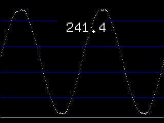 simple digital filter: 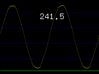 The peaks show some residual HF getting through. Sampling frequency was 8k. I used a sample size of 3 for the filter: SUB math_runAv array1!(), samples%, arrayout!(), count% LOCAL INTEGER n, range, k, b LOCAL FLOAT av range = samples%\2 b = MM.INFO(OPTION BASE) FOR n = MM.INFO(OPTION BASE) TO count% av = 0 FOR k = -range TO samples%-range-1 IF (n+k) < b THEN av = av + array1!(b) ELSEIF (n+k) > count% THEN av = av + array1!(count%) ELSE av = av + array1!(n+k) ENDIF NEXT k arrayout!(n)= av/samples% NEXT n END SUB Jim VK7JH MMedit MMBasic Help |
||||
TassyJim Guru Joined: 07/08/2011 Location: AustraliaPosts: 6100 |
This is a demo of getting power from captured volts and amps. yellow = volts cyan = amps green = power. It was tested on an armiteF4 but should run on a picomite with any resolution display. ' OPTION EXPLICIT OPTION DEFAULT INTEGER OPTION BASE 1 DIM capturesize = MM.HRES * 4 DIM cpp = 2 ' cycles per page DIM FLOAT radppixel = 2*PI*cpp/MM.HRES DIM FLOAT voltarray(capturesize) DIM FLOAT ampsarray(capturesize) DIM FLOAT voltview(MM.HRES) DIM FLOAT ampsview(MM.HRES) DIM FLOAT powerview(MM.HRES) DIM hor(MM.HRES) DIM n, trigger, ampphase DIM FLOAT vs = 0.75, ps = -0.01 DIM k$ FOR n = 1 TO MM.HRES : hor(n) = n : NEXT n FOR n = 1 TO capturesize voltarray(n) = SIN(n*radppixel)*150 ampsarray(n) = SIN(n*radppixel)*50 NEXT n trigger = MM.HRES/2 redraw DO k$ = INKEY$ IF k$<>"" THEN SELECT CASE k$ CASE "<","," ampphase = ampphase + 1 IF ampphase > MM.HRES/2 THEN ampphase = 0 CASE ">","." ampphase = ampphase - 1 IF ampphase <=0 THEN ampphase = MM.HRES/2 END SELECT redraw ENDIF LOOP Sub redraw Local pow, pf! Memory Copy Float Peek( Varaddr voltarray())+trigger*8,Peek( Varaddr voltview()),Mm.hres Memory Copy Float Peek( Varaddr ampsarray())+trigger*8+ampphase*8,Peek( Varaddr ampsview()),Mm.hres math_multiply voltview(),ampsview(),powerview(),Mm.hres pow = Math(Mean powerview()) pf! = pow/(math( sd voltview())*math(sd ampsview())) Math Scale voltview(), vs, voltview() Math Scale ampsview(), vs, ampsview() Math Scale powerview(), ps, powerview() Math Add voltview(), Mm.vres/2, voltview() Math Add ampsview(), Mm.vres/2, ampsview() Math Add powerview(), Mm.vres/2, powerview() Cls Line 0,Mm.vres/2,Mm.hres,Mm.vres/2,1,Rgb(Blue) Pixel hor(), voltview(), Rgb(Yellow) Pixel hor(), ampsview(), Rgb(Cyan) Pixel hor(), powerview(), Rgb(Green) Text Mm.hres/2,30,Str$(pow)+"W "+str$(pf!,2,2)+" pf",cm,1,2 End Sub SUB math_multiply array1!(), array2!(), arrayout!(), count% LOCAL n% FOR n% = MM.INFO(OPTION BASE) TO count% arrayout!(n%)= array1!(n%) * array2!(n%) NEXT n% END SUB The two memory copy lines have wrapped. Jim use < and > to shift the phase of the current. Edited 2023-09-12 14:23 by TassyJim VK7JH MMedit MMBasic Help |
||||
| Frank N. Furter Guru Joined: 28/05/2012 Location: GermanyPosts: 830 |
@Volhout: Thanks for the really interesting link! ...do you really mean a 33K/33K voltage divider??? There I would have a power dissipation of 800mW... @TassyJim: On the secondary side you already have a galvanic isolation... It is too big for my application... Frank |
||||
| Volhout Guru Joined: 05/03/2018 Location: NetherlandsPosts: 4243 |
It actually works.... Using a small common mode choke to measure 230Vac. The 2x 47kohm resistors are not on this board, but connected in the power plug. 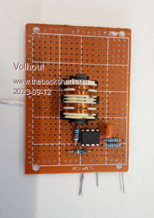 Edited 2023-09-12 18:16 by Volhout PicomiteVGA PETSCII ROBOTS |
||||
| Frank N. Furter Guru Joined: 28/05/2012 Location: GermanyPosts: 830 |
Do you operate the OP with positive and negative supply voltage? Is there a possibility to get along with only one (positive) voltage? Frank |
||||
| Pluto Guru Joined: 09/06/2017 Location: FinlandPosts: 358 |
According to Volhout's schematic above, only +5V supply. LM358 can output almost to 0V with single 5V supply. |
||||
| Volhout Guru Joined: 05/03/2018 Location: NetherlandsPosts: 4243 |
@Jim, I did not investigate your complete power meter program in depth. With such a nice voltage waveform, the filtering you add does not give much extra. Try to RMS both waveforms, and you will see the results are identical. And when not ... blaim is on the filter (really, this is no joke). I am not sure if you need 8kHz. Have been working on several energy meters here and these run on 4kHz, using a ADC with SINC3 filter and modulation frequency trap. These are class 0.2 meters. I will be following this carefully. Both you and Frank. Volhout P.S. one tip. If you capture data in an array, and want to do accurate RMS, you will see errors as result of incomplete waveforms (i.e. 3-3/4 waveforms in the array, not 3 or 4). RMS calculation should be performed on full amount of waveforms to prevent DC errors. There are 2 ways to do this 1/ adjust the sampling frequency to get full waveforms in the array this gives perfect FFT and RMS 2/ capture an array and: - window it for FFT (i.e. Hann) - find zero first and last crossings in the array, and calculate RMS over the cycles between these zero crossings. PicomiteVGA PETSCII ROBOTS |
||||
| phil99 Guru Joined: 11/02/2018 Location: AustraliaPosts: 2135 |
Frank, the waveform you showed on the previous page seems to show significant capacitive coupling between the two windings. The output of Jim's transformer shows the 'flat top' distortion you should see, not the peaks in yours. If you must use that transformer it's possible to reduce the effect of the coupling. 1) Swap active and neutral and check the waveform again. Getting the active end of the primary away from the secondary should help. 2) Put a large capacitor from the voltage reference end of the secondary to ground and a smaller one from the other end to ground. These may swamp the primary / secondary capacitance. If this causes a phase shift subtract it in software. Trial and error will determine the values of the caps. 3) Swap the secondary connections. It might give a small improvement if it gets the measurement end of the secondary further away from the primary. |
||||
| Frank N. Furter Guru Joined: 28/05/2012 Location: GermanyPosts: 830 |
@Pluto: You are right! I didn't look at the picture thoroughly enough - those who can read are clearly at an advantage...  @phil99: 1) Swapping N and L has no effect on the curve. 2) This is my reference voltage generation: 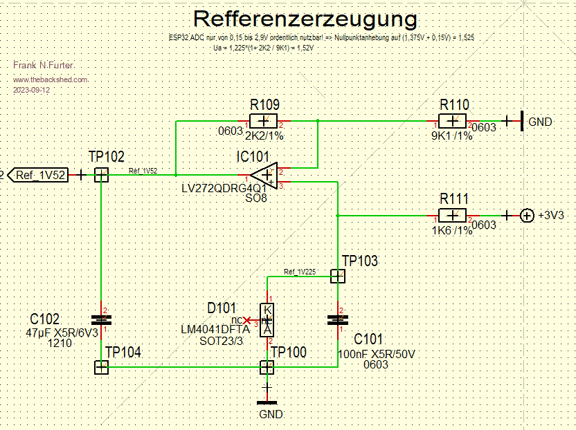 There I used a 47µF for stabilization. Do you think I should make it bigger? 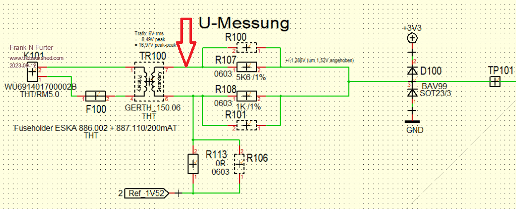 You mean I should connect the second capacitor here? Frank |
||||
| Volhout Guru Joined: 05/03/2018 Location: NetherlandsPosts: 4243 |
@Frank, For an opamp to be stable, it is preferred to have a phase margin of 45 degrees or more. Your opamp (TLV272) phase margin versus capacitove load shows that the maximum capacitive load is 300pF (the 0 ohm series resistor curve). 47uF is FAR too much. Your TLV272 opamp will not operate reliable. 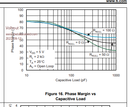 Additionally, if you plan to use the pico ADC is is best to use a LM4040 3V as reference at the VREF pin, and use a 1:1 voltage divider from that reference to create 1.5V. In that case they cannot drift appart. One reference for both. Volhout PicomiteVGA PETSCII ROBOTS |
||||
TassyJim Guru Joined: 07/08/2011 Location: AustraliaPosts: 6100 |
My real program does sample at 4kHz. That gives me room to capture 2.5 seconds for before and after disturbances. The arrays are sized to suit 50Hz and long enough to give good RMS readings. Even thou it is over 30 years since I worked in power distribution, I still have an interest in what's happening. I am waiting for an event to record to see if it is as good as the old systems we had at the substations. Jim VK7JH MMedit MMBasic Help |
||||
| phil99 Guru Joined: 11/02/2018 Location: AustraliaPosts: 2135 |
47µF should be enough. Yes, experiment with values. Too high and it may reduce the voltage accuracy yet it must be much larger than the capacitance between the windings to be effective. Edit Volhout,s method looks like a good compact way to measure the mains. It has the potential for good phase accuracy as the primary circuit is almost totally resistive. If all the resistance is in the active leg the effect of capacitive coupling will be close to zero. As the layout of the windings is visible the the signal end of the secondary can be kept away from the primary. Edited 2023-09-12 22:07 by phil99 |
||||
| Frank N. Furter Guru Joined: 28/05/2012 Location: GermanyPosts: 830 |
@Volhout: ? ...that's just a voltage follower with amplification, isn't it? @phil99: I have now inserted a 10µF at this point: 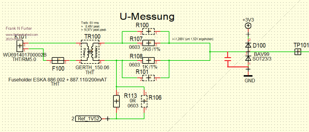 The voltage measurement looks quite acceptable now: 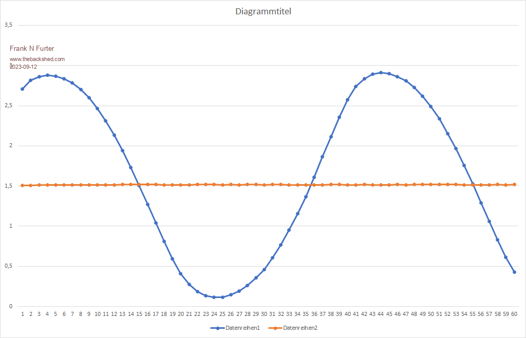 The red line is the measured voltage reference - it is stable up to the 2nd decimal place - only the third decimal place changes. So I measure 1.51XXX every time. Frank |
||||
| Frank N. Furter Guru Joined: 28/05/2012 Location: GermanyPosts: 830 |
I have drawn an ideal sine curve (grey) here: 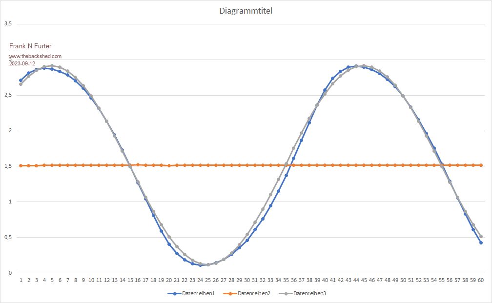 Do you think that is accurate enough??? Frank |
||||
| Volhout Guru Joined: 05/03/2018 Location: NetherlandsPosts: 4243 |
Hi Frank, You have not given any pass-fail criteria. Is it good enough ...? I cannot judge. You have put the zero crossing of both waveforms on top of eachother. - The second zero crossing is roughly 3/4 sampe period wrong (at 40 samples per sinewave is 6.7 degrees). - At this exact moment the amplitude difference between the 2 waveforms is almost 5% of the peak-peak amplitude. This will show up as harmonic distortion in the spectrum. If you run an FFT on the samples it gives you a number for the harmonic content. But the most important question is: Is the waveform the same as the actual mains waveform. The actual mains waveform may show the same distortion, or it may not.... Your transformer does not have to create a perfect sine wave, but it needs to be a good copy of the input signal. This is the input (blue) and the output (red) of my common mode choke circuit. The input is the 230V mains voltage. I used a scope with isolated input channels to prevent lethal voltages on the scope. 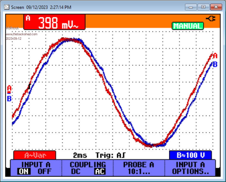 Volhout P.S. the output is leading in phase, not lagging as I would normally expect... Edited 2023-09-12 23:30 by Volhout PicomiteVGA PETSCII ROBOTS |
||||
| phil99 Guru Joined: 11/02/2018 Location: AustraliaPosts: 2135 |
That such a large capacitor was needed after the voltage divider without entirely eliminating the distortion indicates I was wrong. It can't be winding capacitance so I tested a variety of transformers and the largest was less than 1nF between windings, so a 100nF should have fixed it. That leaves core saturation as the most likely cause, which suggests that transformer isn't suitable for 240V 50Hz. This idea can be tested by putting a resistor in series with the primary. Choose a value that reduces the primary voltage to 150V to 200V and see what the output looks like. To see if this is common to small transformers I made the following test circuit using a tiny 1.3VA transformer. The result is much better and is what yours should look like.  Edited 2023-09-13 11:54 by phil99 |
||||
| Mixtel90 Guru Joined: 05/10/2019 Location: United KingdomPosts: 6798 |
IIRC the "proper" VTs that we used to use had quite bulky cores for their burden rating. That may explain it, making it difficult to saturate the core. Given that, avoid toroids as they saturate if you breathe on them. After that it's probably a compromise. The best way is probably to wind secondary first (keep it close to the core for best characteristics), then lots of insulation, then the primary (where it cools better). Split bobbin transformers may not couple the primary and secondary closely enough for good monitoring. All this waffle might explain why VTs cost a lot more than ordinary mains transformers. :) Having said all that, I'd be tempted to try a 30VA or 40VA toroid loaded to 10mA or so. I think you probably need the core size and close coupling (even though the layers are the wrong way round). Mick Zilog Inside! nascom.info for Nascom & Gemini Preliminary MMBasic docs & my PCB designs |
||||
| Frank N. Furter Guru Joined: 28/05/2012 Location: GermanyPosts: 830 |
@Volhout: You are right! At the end of the day, I would like to be able to measure the power to approximately 100W to 200W (500W would possibly also be sufficient). The most important thing is whether power is being generated or consumed at the moment. How can I measure that? I have an oscilloscope and an isolating transformer... Your curves look really very good - I think I have to try your setup too!!! Do I see correctly that you used 150V AC in your simulation? What is the power dissipation of your circuit? I should still have a few Würth common mode choke here... @phil99: I used this transformer here. This is a small 0,33VA transformer... I could put a second transformer in series for a test - should that do anything? Otherwise I have to look for suitable resistors here... Frank |
||||
| Mixtel90 Guru Joined: 05/10/2019 Location: United KingdomPosts: 6798 |
If you use resistors put a series string of them together so that you don't exceed their voltage rating. If you take the input impedance of the 'scope (usually 1M) into consideration then you can make up a potential divider so that the output voltage can't exceed the 'scope's input rating. The current through the resistors will be low so they won't get hot. I used to thread HV strings through fish tank airline tubing when measuring a few thousand volts. :) Mick Zilog Inside! nascom.info for Nascom & Gemini Preliminary MMBasic docs & my PCB designs |
||||
| phil99 Guru Joined: 11/02/2018 Location: AustraliaPosts: 2135 |
Yes that would be ideal. With such a tiny transformer (0.33VA) the primary resistance will be very high, the 1.3VA one measures 1.9k and the smaller they are the higher it gets. So you don't have to alter the rest of the circuit also put the secondary windings in series, making sure they have the same phasing or there will be no output.. |
||||