
|

|
Forum Index : Microcontroller and PC projects : Bought a 16 MB Ram pico but
| Author | Message | ||||
| Pluto Guru Joined: 09/06/2017 Location: FinlandPosts: 359 |
Mick, I just made a simple test: setpin 31,ain 'ADC 0 GP26 print pin(31) setpin 32,ain 'ADC 1 GP27 print pin(32) setpin 34,ain 'ADC 2 GP28 print pin(34) With all inputs disconnected: GREEN module: 0.2475335775 0.3416849817 0.3287912088 BLACK module: 3.3 3.3 3.3 ADC0 to GND: GREEN module: 0.01383394383 0.3344322344 0.3317460317 BLACK module: 3.3 3.3 3.3 No wonder I had problems! Pluto |
||||
TassyJim Guru Joined: 07/08/2011 Location: AustraliaPosts: 6100 |
The Black boards have a solder link near GP26 which links Vref to 3.3V Closing that gives you good ADC functions. I found that easier than extra headers etc. My black boards runs the current ADC CRO software without any issues. If anything, I would consider the Black boards have less jitter in the traces. Jim VK7JH MMedit MMBasic Help |
||||
| Pluto Guru Joined: 09/06/2017 Location: FinlandPosts: 359 |
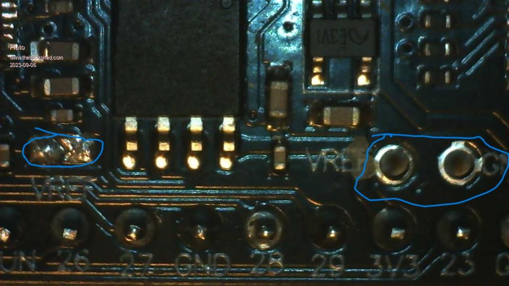 At the connection points on the right I measure about 0.02V. Shouldn't this be Vref 3.3V? On the left there is an open "solder-blob" connection. Should it be closed for using the onboard 3.3V as Vref? I always thought the connector on the right was an output for Vref, but could it be an input for Vref? --Leave the "blob" open and supply your own Vref to the connectors --or close the "blob" and use the onboard 3.3V as Vref. Needs some more testing...but I have to leave it for tomorrow.  |
||||
| Pluto Guru Joined: 09/06/2017 Location: FinlandPosts: 359 |
Thanks Jim! Didn't see your post before I saved my post. The answers come before the question is asked. That's what I call rapid service. Your answer seems to be in line with my guesses.  Thanks and good night (at least here, when I don't need to have nightmares about malfunctions in ADCs.) Pluto |
||||
| okwatts Regular Member Joined: 27/09/2022 Location: CanadaPosts: 59 |
In the interest of showing another version I have been using the WeACT RP2040 which has most of the same features, 16MB Flash, USB-C but is not exactly pin-compatible with the genuine Pico. I have been using it at nominal speed but I have had it operate at 378MHz successfully as well. Since I am late to MMBasic I started with the PicoMite in its various forms. I used this particular version as a Pico replacement for Geoff's MicroMite LCD Backpack. I attach the pinout and I purchase this in Canada at the following https://universal-solder.ca/product/rp2040-pico-board-16mb-raspberry-pi/ 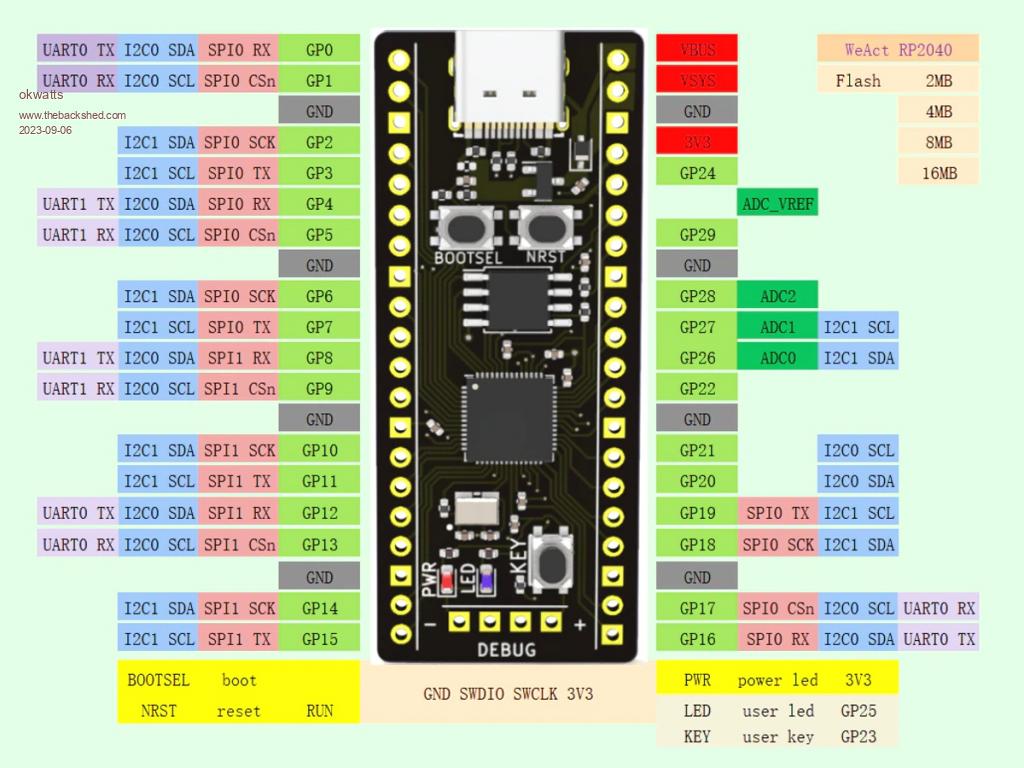 For those who are capable of producing a board ( I have no design or KICAD experience) this would be a boon to me and perhaps others rather than having to wire this point to point like I did. 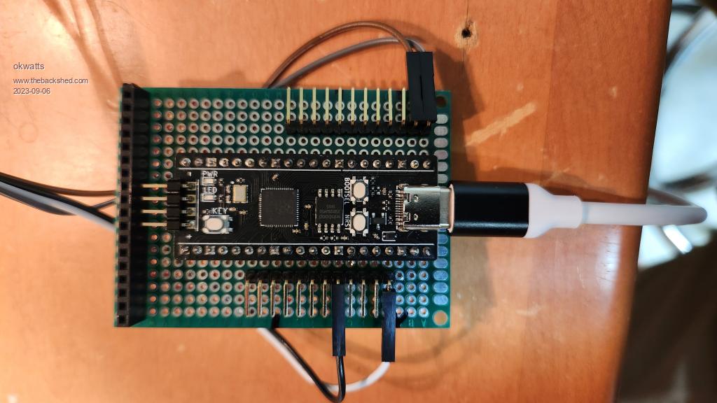 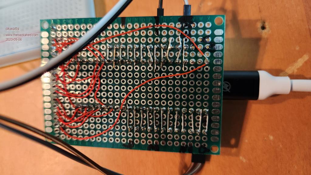 |
||||
| Mixtel90 Guru Joined: 05/10/2019 Location: United KingdomPosts: 6798 |
There is no VREF source resistor at all on the YD-RP2040 black board. You can simply blob the link. That will connect VREF directly to 3V3 (not too horrendous with a linear regulator. There is 100nF decoupling in place to reduce regulator noise). You can fit a 0603 size 220R onto the link and a larger cap into the VREF and GND holes to get lower noise performance. You can fit 220R as above, but a LM4040-3V reference into the VREF and GND holes to get a 3V reference. You can use an external R,C network from 3V3 to VREF. You can inject a precision voltage of anything up to 3V3 directly into VREF (this needs to be powered from the 3V3 line so that it gets shut down with the supply). =========================== @ okwatts That board is close enough to be used on most of the Pico and PicoMite patch board layouts. You may have to cut tracks where GP29 and GP24 are in some cases, but that's all. Note - although that is also black it isn't a YD-RP2040. :) Edited 2023-09-06 16:54 by Mixtel90 Mick Zilog Inside! nascom.info for Nascom & Gemini Preliminary MMBasic docs & my PCB designs |
||||
TassyJim Guru Joined: 07/08/2011 Location: AustraliaPosts: 6100 |
The board shown has a lot of gotcha's from pin 30 onwards. Starting with GP26 where the RUN reset button would go. Jim VK7JH MMedit MMBasic Help |
||||
| Mixtel90 Guru Joined: 05/10/2019 Location: United KingdomPosts: 6798 |
Oh yes! I hadn't spotted that they'd moved all the ADC inputs! Nope, sorry, WeAct - I wouldn't bother with that board. It breaks too many rules. I thought the YD-2040 was a bit out, but as I look at it more I think they made some good choices. I just with they'd used faster flash. Mick Zilog Inside! nascom.info for Nascom & Gemini Preliminary MMBasic docs & my PCB designs |
||||
| okwatts Regular Member Joined: 27/09/2022 Location: CanadaPosts: 59 |
Agreed that that the pins being moved from pin 30 on is an issue for the typical pico add-ons but for my purpose as a Micromite LCD backpack replacement it will work fine. I can use it for Geoff's Air Quality monitor. 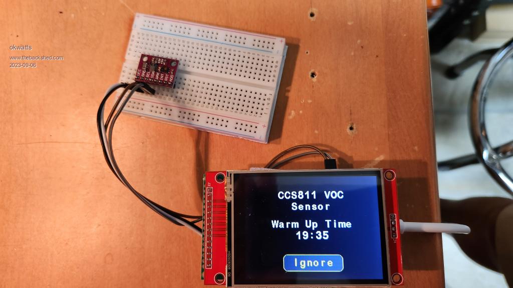 |
||||
| Pluto Guru Joined: 09/06/2017 Location: FinlandPosts: 359 |
My YD-RP2040 black board works as intended after closing the link as advised by Mick and Jim. Thanks to all of you in the shed for marvellous support and inspiration.  Pluto |
||||