|

|
Forum Index : Microcontroller and PC projects : Solar Battery fridge Controller
| Author | Message | ||||
| lizby Guru Joined: 17/05/2016 Location: United StatesPosts: 3150 |
Ok, 1K resistors have been placed in those spots. PicoMite, Armmite F4, SensorKits, MMBasic Hardware, Games, etc. on fruitoftheshed |
||||
| Bleep Guru Joined: 09/01/2022 Location: United KingdomPosts: 511 |
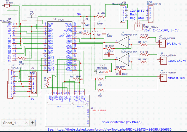
I also just remembered that I added two small 100nF capacitors, one across the 100K and the other across the 560K resistors on the OpAmps, again to get rid of ripple & interface, if you want to make your diagram completely correct. Regards Kevin |
||||
| lizby Guru Joined: 17/05/2016 Location: United StatesPosts: 3150 |
Thanks, Kevin. I've added those. PicoMite, Armmite F4, SensorKits, MMBasic Hardware, Games, etc. on fruitoftheshed |
||||
| lizby Guru Joined: 17/05/2016 Location: United StatesPosts: 3150 |
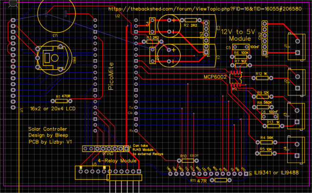
Current state:   Zipped EasyEDA folder: SolarController.zip Gerbers: SolarController_2023-07-05_Gerber.zip PicoMite, Armmite F4, SensorKits, MMBasic Hardware, Games, etc. on fruitoftheshed |
||||
| lizby Guru Joined: 17/05/2016 Location: United StatesPosts: 3150 |
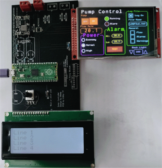
Just a tease. I'm not close to hooking up any relays or inputs: 20x4 LCD with ILI9488 running Geoff's guidemo.bas altered for 480x320 LCD.  Many thanks to Kevin. It's been fun just getting to this point. There will be a V2 of the PCB--I omitted 0V for the backlight on the 20x4, and Kevin's last suggestions didn't make it to the PCB (though I will alter this board to accomodate them). PicoMite, Armmite F4, SensorKits, MMBasic Hardware, Games, etc. on fruitoftheshed |
||||
Quazee137 Guru Joined: 07/08/2016 Location: United StatesPosts: 571 |
Looks like a FUN project. I am in a HOA Condo. What I need it a system that charges the battery from 9PM to next day 4PM and auto switches at 4PM from mains feed to my fridge from inverter then back to mains at 9PM. Two would save me al lot because I am on a 2 tier rate usage. $0.26 1st and $0.37 2nd. HOA now allows solar but the local power company gets to decide the wattage. I have 48VDC 20AM LiFePO batteries for my E-Trikes that I can make use of. Kind of a store and forward system. Also good when we lose power. I'm looking to build two. The 2nd for a portable AC as my main HVAC eats 4.2KWs when the compressor is on. I have been pricing 48VDC inverters starting at 800 watts up to 2000. I need to see if the HOA has a problem with me putting 1000 to 2000 solar on my patio roof that they say is up to me to fix as its not common property so it's mine. I have been playing with the Waveshare RP2040-Zero with SPI display and SD and zero crossing will be a good start for me. Quaze137 |
||||
| lizby Guru Joined: 17/05/2016 Location: United StatesPosts: 3150 |
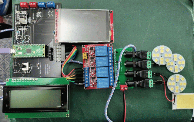
I agree--Kevin's project is fun and interesting. If I get it fully implemented, my use will also be different from his. Unfortunately, I don't have two-tiered electricity costs, and I think my fridge and freezer draw too much current. I have 200 watts of solar, with the possibility of adding more, and some 18650 12V and 24V battery packs to play with. It's just a learning experience for me. Here's the PCB with a 4-relay module added (and working--12 Volts only):  The 8-pin header above the connector to the relay uses the same data pins plus two more, so it could connect to a 6-relay module. It could also have an RJ45 adaptor plugged into it to connect to a remote relay module through an ethernet cable. That's what I would use if I were connecting mains. I have an RJ45 adaptor to relay-module PCB. I'm still waiting for some resistors to finish (and time). PicoMite, Armmite F4, SensorKits, MMBasic Hardware, Games, etc. on fruitoftheshed |
||||