|

|
Forum Index : Microcontroller and PC projects : Colour Maximite 1.5? or something
| Author | Message | ||||
| lizby Guru Joined: 17/05/2016 Location: United StatesPosts: 3150 |
I received my boards. They look beautiful. I inserted a CR2032 battery, plugged in a male to male USB A cable--PCB & PC--and pasted PicoMiteVGAUSBV5.09.00b3.uf2 to the drive presented. I removed the USB A cable and plugged in a USB C cable (PCB) to USB A (PC), opened TeraTerm, connected to the serial port, and voila, a ">" prompt (serial port was already set at 115200). I entered the OPTIONs printed on the board, and all worked except that "OPTION RTC AUTO" needed to be "OPTION RTC AUTO ENABLE". I plugged in the VGA, and CLS RGB(RED) worked, and CLS RGB(BLUE). With F10 (AUTOSAVE) I downloaded Volhout's Programming Challenge sokoban.bas, and it worked. Congrats, Peter, on this terrific addition to the MMBasic PCB stable. When I have tested the remaining PCBs, I will PM those who have requested one about the cost, payment, and address for mailing. PicoMite, Armmite F4, SensorKits, MMBasic Hardware, Games, etc. on fruitoftheshed |
||||
| lizby Guru Joined: 17/05/2016 Location: United StatesPosts: 3150 |
I flashed all 5 PCBs. All come up with the flashing red led, but one of them says "USB malfunctioned" (or words to that effect. The other 4 all worked through setting of options and CLS RGB(red). I've reflashed the non-working one 5 times, including with the erase.uf2 file. No errors are reported, the red LED flashes as per normal, but no USB COMM port is available. Anything else I should try on that one? PicoMite, Armmite F4, SensorKits, MMBasic Hardware, Games, etc. on fruitoftheshed |
||||
bigmik Guru Joined: 20/06/2011 Location: AustraliaPosts: 2914 |
Hi Lizby, I would guess that it would have to be something associated with the USB-C connector or the CH340C and components nearby. Check for solder shorts or missed solder connections. Kind Regards, Mick Mick's uMite Stuff can be found >>> HERE (Kindly hosted by Dontronics) <<< |
||||
| matherp Guru Joined: 11/12/2012 Location: United KingdomPosts: 9115 |
Agreed, it can only be 4 components or the wiring between them: USB-C connector, CH340, R31 or R32 Edited 2024-02-28 18:40 by matherp |
||||
| lizby Guru Joined: 17/05/2016 Location: United StatesPosts: 3150 |
I have looked fairly carefully over the entire board with a magnifying glass (with focus on the USB-C socket), and nothing is evident. I will look again at those particular components. PicoMite, Armmite F4, SensorKits, MMBasic Hardware, Games, etc. on fruitoftheshed |
||||
| lizby Guru Joined: 17/05/2016 Location: United StatesPosts: 3150 |
Reinspection with a magnifying glass did not reveal any obvious problems with this board. Flashing again made no difference--USB device not recognized. Are console pins somehow enabled with this firmware--or is it possible to get a test version with console pins set up? Another question: is it ok to plug ear buds in to the audio socket? PicoMite, Armmite F4, SensorKits, MMBasic Hardware, Games, etc. on fruitoftheshed |
||||
| matherp Guru Joined: 11/12/2012 Location: United KingdomPosts: 9115 |
They are but it is irrelevant. If I understand your issue correctly the board isn't registering the USB port with your computer? The CH340 should do this even with no firmware in the RP2040. Of course it wouldn't respond but you could short pins 2 and 3 on the ch340 with a screwdriver then should should get an echo on teraterm for anything you type. Until this works the Pico is irrelevant. If you have a USB-C to USB-A adapter then you can buzz out the middle two pins to pins 5 and 6 on the ch340. You should see 2 or 3 ohms on the correct pairs |
||||
| lizby Guru Joined: 17/05/2016 Location: United StatesPosts: 3150 |
The board isn't registering the USB port with the USB_C port connected to the PC (as it successfully did with the other 4 boards). When connecting USB_A to USB_A, I could copy the uf2 firmware as with the others--apparently successfully, since the red LED is flashing once a second. PicoMite, Armmite F4, SensorKits, MMBasic Hardware, Games, etc. on fruitoftheshed |
||||
| lizby Guru Joined: 17/05/2016 Location: United StatesPosts: 3150 |
Ok, with the board powered through the USB_A to USB_A connector, with GP8 & GP9 and GND going to a USB-TTL module, I have console. PicoMite, Armmite F4, SensorKits, MMBasic Hardware, Games, etc. on fruitoftheshed |
||||
| matherp Guru Joined: 11/12/2012 Location: United KingdomPosts: 9115 |
OK so you have narrowed it down completely to the CH340 circuit and you know that GP8 and GP9 aren't compromised. You should see the uart signals from your USB-TTL module on pins 2 and 3 of the CH340? Check the power to the CH340 - Gnd on pin 1, 3.3 on pins 4 and 16. If that is OK the personally what I would do is swap a ch340 from a known good board but only if you are confident in soldering the SOP chip |
||||
bigmik Guru Joined: 20/06/2011 Location: AustraliaPosts: 2914 |
Hi Lizby, It is possible that incorrect values have been soldered onto the board. Check R36 & R37 are both 27R. And check R31, R32 are 5k1 and R33 is 1M. On the CH340 check you have 3v3 across Pins 1 and 16. Looking into the USB-C connector do the pins look OK (compare to the others). I am happy to look at the PCB for you but I am as far an away from you as it’s possible to be in the world and postage would be prohibitive and likely more than the cost of the board for 2 ways. I personally don’t like the CHxxx family of Uarts and my first choice is always the FT231. This prejudice probably extends from the early days when these type of chips were very hard to get Window 7 etc to talk to them, no doubt things are different now. Regards, Mick Mick's uMite Stuff can be found >>> HERE (Kindly hosted by Dontronics) <<< |
||||
| Thexder Newbie Joined: 31/01/2024 Location: United StatesPosts: 1 |
Hello everyone! Longtime lurker here, since the first Maximite anyway. Have chosen to keep my ears open and my mouth closed and can say that I have learned much from all of you. Thank you. Ordered up MatherP's 1.5 boards and can report 4 out 5 worked flawlessly. One is just DOA at the moment, my diagnostic equipment is not currently with me. Solder joint somewhere no doubt. Will get it. Am looking forward to the CMM2 boards as well. I will be here quietly reading in the background - am honestly not sure I have much value to add to this group - you all are quite extraordinary - at the very least you are tough acts to follow! I am an enterprise IT guy so perhaps I can be assist there somewhere. Great work MatherP and Geoff - and too all the many others that have lit the spark for me once again. Prost! Gary n8mdl |
||||
| matherp Guru Joined: 11/12/2012 Location: United KingdomPosts: 9115 |
All Please note, there will be a version 1.1 board soon so you might want to hold off further orders for a week or so. Changes are to go back to a 8-pin DS3231 as those are both cheaper and in stock replace edge connector with one that is in stock and reverse the pin-1 end Isolate audio ground to reduce noise floor of audio output. Reduce the number of "extended" range components to reduce cost 3.81mm speaker screw terminals rather than 2.54mm 103bf8ee-3fec-4021-b184-d469d4d798f6.pdf  Edited 2024-03-01 04:20 by matherp |
||||
Grogster Admin Group Joined: 31/12/2012 Location: New ZealandPosts: 9306 |
I knew it was wise to only get five myself in my prototype run!   Smoke makes things work. When the smoke gets out, it stops! |
||||
| lizby Guru Joined: 17/05/2016 Location: United StatesPosts: 3150 |
Hmmm, R31, R32, and R33 have the values you say on a working PCB, but on the non-working one, R32 and F33 are correct, but R31 is 2k8. I'm not sure I have the skill to replace that. Power seems good from the USB_C socket--the board boots up and console is available on GP8 and GP9. I don't have the ability to swap the CH340--I'd probably end up with 2 bad boards. PicoMite, Armmite F4, SensorKits, MMBasic Hardware, Games, etc. on fruitoftheshed |
||||
bigmik Guru Joined: 20/06/2011 Location: AustraliaPosts: 2914 |
Hi Lizby, That ‘could’ be your problem as the different resistor value would report an incorrect device to the PC (or charge capability). Removing the resistor isn’t that difficult, add more solder to both sides and hit both ends with a HOT soldering iron and it will move easilly. To solder a new SMD clean the pads with solder wick so they are as clean as possible, put a small blob (not too much) of solder on ONE pad Use tweezers and place the new resistor over the pads and hit the end with the blob, it should hold Then properly solder the other end, then redo the first end. If you are really unsure about soldering the SMD use a standard 5k1 resistor and identify the pad that is going to the connector (the non GND one) and solder one leg of the standard resistor to it and the other end to a suitable GND point. It may be best to solder the GND leg first to not put too much stress on the tiny SMD pad. Regards, Mick Mick's uMite Stuff can be found >>> HERE (Kindly hosted by Dontronics) <<< |
||||
| matherp Guru Joined: 11/12/2012 Location: United KingdomPosts: 9115 |
Revised gerbers for V1.1 now posted to github H/W changes as above. No change in functionality |
||||
| matherp Guru Joined: 11/12/2012 Location: United KingdomPosts: 9115 |
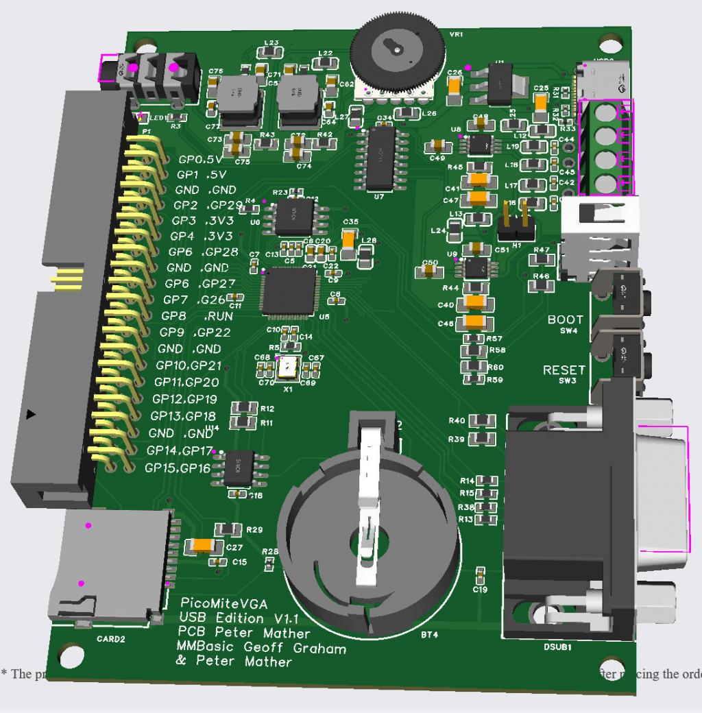
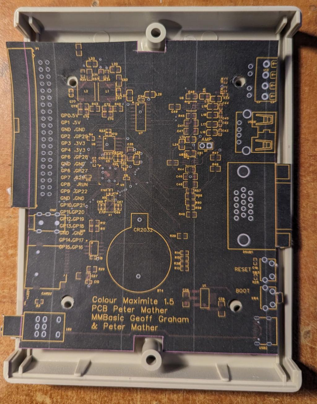
I've found a nice box for the Colour Maximite 1.5. MULTICOMP MCRM2015S CASE, DESKTOP, ABS, 30X130X100MM Just need to spread out the components on the PCB a bit to reach the edges. Unfortunately to get everything along the two edges the length is 110mm and the width to fit the box is 90mm  |
||||
| Mixtel90 Guru Joined: 05/10/2019 Location: United KingdomPosts: 6786 |
Yeah.... why can't they make enclosures in just the right size, eh? ;) . Mick Zilog Inside! nascom.info for Nascom & Gemini Preliminary MMBasic docs & my PCB designs |
||||
| Volhout Guru Joined: 05/03/2018 Location: NetherlandsPosts: 4233 |
Move the audio volume potmeter to the other side of the 40pin header. Volhout PicomiteVGA PETSCII ROBOTS |
||||