|

|
Forum Index : Microcontroller and PC projects : PicoMite: PicoGAME VGA development
| Author | Message | ||||
| Mixtel90 Guru Joined: 05/10/2019 Location: United KingdomPosts: 6822 |
You're doing fine, Tom. :) Your circuit and calculations are impeccable. I just wanted to get a bit of load on the thing. At the moment my known load (on the prototype) is only about 100mA plus another 80mA with both joystick fire buttons pressed (pin 6 pulled low). I'll measure this again later. The controllers only draw about 2mA each and they won't normally be used with the fire buttons so the buttons give a useful maximum load. 180mA takes it over the rating of the MCP1701, but it's unlikely that both fire buttons will be pressed continually - and I'm going to try to drop that 80mA to just under 50mA later today anyway. 3off 47R in parallel will draw 210mA. If your regulators will keep an output of about 3V3 at that then they'll definitely be fine. You can expect them to warm up a bit as they'll dissipate about 0.36W with a 5V supply. The maximum power dissipation of the package is around 0.9W at a 40 degrees C ambient, so there's no problem. In any case the device will shut down at 140C to protect itself. :) Mick Zilog Inside! nascom.info for Nascom & Gemini Preliminary MMBasic docs & my PCB designs |
||||
| thwill Guru Joined: 16/09/2019 Location: United KingdomPosts: 4047 |
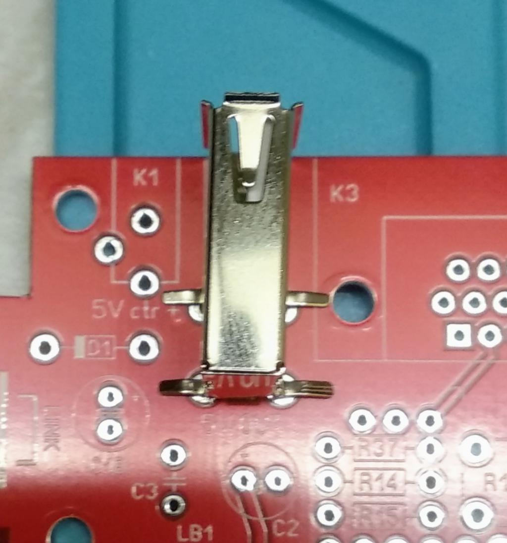
Thanks Mick & Bill. Mick regarding the USB-A socket. The attached photo shows that all the holes are basically aligned correctly for the AliExpress component (which I can only find in this orientation). The legs however are 1.5mm wide and thus need bigger holes or slots, personally I would look at adding another 0.2mm to that to provide some wiggle room.  Best wishes, Tom Game*Mite, CMM2 Welcome Tape, Creaky old text adventures |
||||
| thwill Guru Joined: 16/09/2019 Location: United KingdomPosts: 4047 |
Hi Volhout, WAV feels "era inappropriate" plus it requires a file-system and I'm still looking at building a handheld without an SD card at some future point. I'm encoding music and sound FX as notes which I play with PLAY SOUND on a software interrupt. You can see it in practice here: https://github.com/thwill1000/mmbasic-polar-snake/blob/main/polar-snake.bas This version reads data from a CSUB but in my latest effort I've switched to using DATA so it works on MMB4W. Anyway I've joined a 1-bit music forum and hopefully someone there will be able to give me some direction. Best wishes, Tom Game*Mite, CMM2 Welcome Tape, Creaky old text adventures |
||||
| Mixtel90 Guru Joined: 05/10/2019 Location: United KingdomPosts: 6822 |
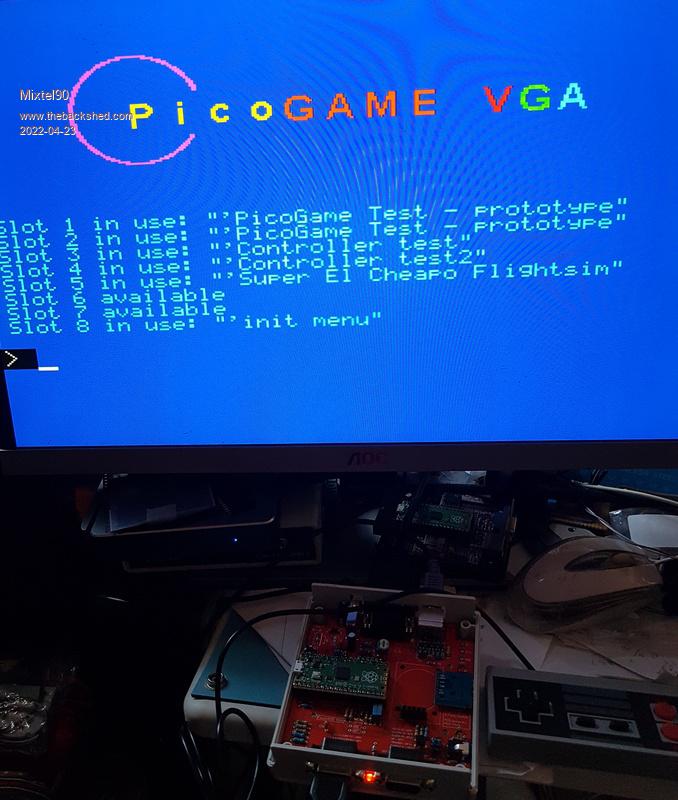
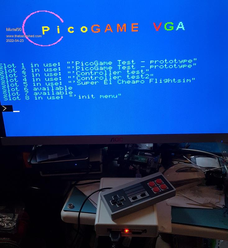
I'd already improved the alignment of the USB-A fixing holes so the "back" holes line up now. I'll change the pads to 2.5mm outside, 1.65mm inside. I don't want them to be too sloppy with the "official" sockets. EDIT: R33 and R35 can be increased in value from 68R to 150R. This reduces the "Fire button" current to 22mA maximum. This is well within the rating of tactile switches and should keep the total current down to about 144mA - within the rating of the MCP1701. Note that this reg is fine anyway if the controllers are used rather than switch-type joysticks.   Edited 2022-04-23 18:57 by Mixtel90 Mick Zilog Inside! nascom.info for Nascom & Gemini Preliminary MMBasic docs & my PCB designs |
||||
| thwill Guru Joined: 16/09/2019 Location: United KingdomPosts: 4047 |
It's looking good Mick. I finally have (an approximation of) all the parts to finish my prototype build, maybe later today. I've also made some preliminary enquiries about sandwiching the finished item between two pieces of transparent acrylic. Best wishes, Tom Game*Mite, CMM2 Welcome Tape, Creaky old text adventures |
||||
| Mixtel90 Guru Joined: 05/10/2019 Location: United KingdomPosts: 6822 |
A plastic sandwich should be easy enough to do. It's only 2 rectangles of plastic and some spacers & screws. You could even make them 105mm square to make cutting easy. I'd avoid using the hole to the rear of the micro SDcard module as it won't be there on the next version. The case is pretty reasonable from RS, but unless you are ordering other stuff there's a 4.95 UKP postage charge. The case I got was 6.91 UKP +VAT. There are 3 colours (Hammond part numbers but you can search on RS): White 1593WGY (the one I got) Black 1593WBK Transparent blue 1593WTBU (I have one of these on back order 'cos it's so cool!) Mick Zilog Inside! nascom.info for Nascom & Gemini Preliminary MMBasic docs & my PCB designs |
||||
| thwill Guru Joined: 16/09/2019 Location: United KingdomPosts: 4047 |
I tested all my "Chinese" 1700 3302E regulators and they all have outputs closer to 3.5V than 3.3V. Is this expected, or have I got part of an off-spec batch, or something mislabeled? Is a 3.3V vs. 3.5V difference likely to matter? Best wishes, Tom Game*Mite, CMM2 Welcome Tape, Creaky old text adventures |
||||
| phil99 Guru Joined: 11/02/2018 Location: AustraliaPosts: 2141 |
That is within tolerance if lightly loaded, 3.6V is the upper limit. Put about 100mA load on and see what it is then. 27 to 47 ohms should be near enough. |
||||
| thwill Guru Joined: 16/09/2019 Location: United KingdomPosts: 4047 |
Thanks Phil. It's 3.5V with a 47R resistor, the same as with 15.7R (3 x 47R in parallel). Best wishes, Tom Game*Mite, CMM2 Welcome Tape, Creaky old text adventures |
||||
| Mixtel90 Guru Joined: 05/10/2019 Location: United KingdomPosts: 6822 |
If you are nervous about it you could try a spare BAT85 schottky diode in series with the output. They are ok up to almost 200mA and, at the top end of the range, will drop about 0.6V (less at lower currents). It will mess up the regulation, but that's not very important in this case (it will only affect the analogue inputs). It sounds like those regs are just on the high side (or wrongly marked 3V5 versions). Are they ok with no load? Mick Zilog Inside! nascom.info for Nascom & Gemini Preliminary MMBasic docs & my PCB designs |
||||
| Volhout Guru Joined: 05/03/2018 Location: NetherlandsPosts: 4262 |
Tom, Not sure about the regulator, but the mcp1700 are normally very accurate. When you have samples that are 3.5v I would not use them without carefull testing. I personally would dispose of them. My worry: what happens when the input voltage is 6v? Or 4.5 Do they regulate voltage to 3.3v, or only output 3.5v at 5v input. In that case they are just as good as 2 diodes in series. Useless.. Volhout PicomiteVGA PETSCII ROBOTS |
||||
| Mixtel90 Guru Joined: 05/10/2019 Location: United KingdomPosts: 6822 |
Strange... I thought some colours looked wrong. :( The prototype board, in addition to having red/blue reversed also has the greens reversed. Two ways round this. Either butcher the pcb tracks to GP19 & GP20 on the back (not bad to do) or cross over the two resistors R12 and R16. It looks like I swapped over the order of GP18-GP21 when laying out the PCB. It's fixed for the next version. I'm mostly doing final testing & tidying up now. Providing I don't come up against anything too horrible I hope to be posting the new Gerbers & documentation sometime during the next few days. Mick Zilog Inside! nascom.info for Nascom & Gemini Preliminary MMBasic docs & my PCB designs |
||||
| Volhout Guru Joined: 05/03/2018 Location: NetherlandsPosts: 4262 |
@mick, Something completely different. The picomite manual mentions PASM, PREVAS etc.. tools to develop PIO code. But these are not available from Geoff's website. Where can I find these ? Volhout Reason I ask is that the MMBasic code does not give me the features to decode frequency modulated signals. I want the PIO to do this for me. I have some example PIO code already (from python environment), but need to put is in MMBasic. PicomiteVGA PETSCII ROBOTS |
||||
| Volhout Guru Joined: 05/03/2018 Location: NetherlandsPosts: 4262 |
edit - deleted as it is double Edited 2022-04-25 05:19 by Volhout PicomiteVGA PETSCII ROBOTS |
||||
| Mixtel90 Guru Joined: 05/10/2019 Location: United KingdomPosts: 6822 |
Try these, Volhout: https://www.thebackshed.com/forum/ViewTopic.php?TID=14401&PID=179297#179297#179297 I'm pretty sure they are ok. :) Mick Zilog Inside! nascom.info for Nascom & Gemini Preliminary MMBasic docs & my PCB designs |
||||
| thwill Guru Joined: 16/09/2019 Location: United KingdomPosts: 4047 |
The one I tested "thoroughly" seems to have a stable output of 3.4V-3.5V over the input range 4-6V with loads of 0-200mA. I spoke with a friend with 30+ years experience of electronics design (and I'm not saying you don't have your own share) and he suggested they were almost certainly knockoffs of some sort but that didn't mean they weren't adequate for the task and seemed to have no qualms, though presumably he wouldn't use them in a mission critical device. I'll let you know how I get on. Best wishes, Tom Game*Mite, CMM2 Welcome Tape, Creaky old text adventures |
||||
| Mixtel90 Guru Joined: 05/10/2019 Location: United KingdomPosts: 6822 |
At worst you'll lose a 3.60 UKP Pico. I bet they are either out of spec 3V3s or re-marked 3V5s. In either case, if they work I'd risk them. Test the one you intend to use at low, medium and high current. Say, loads of about 1K5 (2.2mA), 47R and 15.67R (3x47R in parallel). If they will handle those with a 4-6V input voltage range then they'll definitely be fine. If you are fitting the LED there's not likely to be a problem at low current as there'll always be at least 7.5mA load even without the Pico. That will always draw well above 3mA so we can guarantee 10mA, which is the usual minimum load for maximum stability with even the worst regulators. ---------------------------------------------------------- Latest info for those building the prototype: PicoGAME - prototype.zip Edited 2022-04-25 17:02 by Mixtel90 Mick Zilog Inside! nascom.info for Nascom & Gemini Preliminary MMBasic docs & my PCB designs |
||||
| Volhout Guru Joined: 05/03/2018 Location: NetherlandsPosts: 4262 |
Test with an oscilloscope at the output. They may be good 3.3v regulators, but may be oscillating, if not decoupled. Input capacitor and output capacitor are essential. And they need to be close to the pins. Maybe you should remove the pico from its socket, solder thevregulator to the board, with all capacitors on the board. And only place the pico when you are confident. PicomiteVGA PETSCII ROBOTS |
||||
| thwill Guru Joined: 16/09/2019 Location: United KingdomPosts: 4047 |
Thanks Volhout, I did give the one I was testing a poke with my "toy" oscilloscope and observed no oscillations in the output. All my testing has been done with 1uF (tantalum, 'cause that's what I've got) capacitors on input and output as shown in the circuit diagram I posted previously. Mick, regarding capacitors I note that on the PicoGAME schematic (assuming I am reading it correctly, which is doubtful) there is no decoupling capacitor between the regulators's 3V3 output and the Pico's 3V3 input ? Best wishes, Tom Edited 2022-04-25 20:35 by thwill Game*Mite, CMM2 Welcome Tape, Creaky old text adventures |
||||
| Mixtel90 Guru Joined: 05/10/2019 Location: United KingdomPosts: 6822 |
I didn't bother as the Pico already has a 47uF X5R capacitor on board and the reg is pretty close to it. :) Mick Zilog Inside! nascom.info for Nascom & Gemini Preliminary MMBasic docs & my PCB designs |
||||