|

|
Forum Index : Microcontroller and PC projects : pic32MZ EF 100 pin board sn-7x
| Page 1 of 2 |
|||||
| Author | Message | ||||
| isochronic Guru Joined: 21/01/2012 Location: AustraliaPosts: 689 |
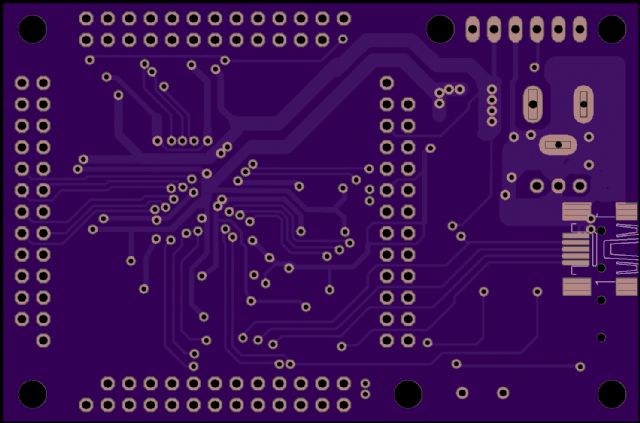
I have polished off the prototype so this is the "goer" stage, it is a simple board that supplies a MZ EF (100 pins) and its anciliaries, simple power supply for 12v operation, and direct usb and also usb-serial bridge comms. The prototype worked OK but using the pcb to dissipate a watt of heat is probably always going to be marginal in aus conditions, so the initial regulator has been changed to a old warhorse 7805 TO-220 so it can be bolted to a metal case etc. Also the 24 Mhz crystal is dropped in favour of a silicon oscillator which can be left off if wanted. Also the usb-serial bridge was a little dated so a mcp2221a can now be used, which requires a lot less components around it (no crystal needed) and installs automatically in win10. The pcb accommodates either. A quick photo with a sd card size adapter for size comparison : and a schematic [I have not changed the USB-direct so I guess it would run MMbasic to a USB console as before.] and some tiny thumbnail electride code runs during a "first light": Electride 2.0 PIC32MZ EF G, S, R, L ? >L PROGRAM temperaturedouble DOUBLE celsius, fahr, step INTEGER*4 i FORMAT (2F12.4,/) step = 20.0 fahr = 0.0 DO 10 i = 1, 11 fahr = fahr + step celsius = 5.0 * ( fahr - 32.0 ) / 9.0 WRITE (6,0) fahr, celsius 10 CONTINUE END Run.. 20.0000 -6.6667 40.0000 4.4444 60.0000 15.5556 80.0000 26.6667 100.0000 37.7778 120.0000 48.8889 140.0000 60.0000 160.0000 71.1111 180.0000 82.2222 200.0000 93.3333 220.0000 104.4444 ^ ... PROGRAM defaultformat C INTEGER*1 a INTEGER*2 b INTEGER*4 c REAL d DOUBLE e CHARACTER*1 f CHARACTER*15 g a = 32 b = 4321 c = 1222333444 d = 1.123456 e = 1.12345678 f = 'Y' g = 'Hello, world' PRINT *, "start" PRINT *, "a = ", a PRINT *, "b = ", b PRINT *, "c = ", c PRINT *, "d = ", d PRINT *, "e = ", e PRINT *, "f = ", f PRINT *, "g = ", g PRINT *, "finish" END \ start a = 32 b = 4321 c = 1222333444 d = 1.123456 e = 1.12345678 f = Y g = Hello, world finish These pcbs can be panelised 2 to the 4x4" format so they are very inexpensive in bulk. |
||||
| JohnS Guru Joined: 18/11/2011 Location: United KingdomPosts: 3801 |
Plans for selling them pre-built? Who/what/where/when/price? John |
||||
| robert.rozee Guru Joined: 31/12/2012 Location: New ZealandPosts: 2350 |
looks like a really nice clean design  i assume the pinouts don't preclude running the "mmbasic-extreme" code that is currently being worked on by others? i assume the pinouts don't preclude running the "mmbasic-extreme" code that is currently being worked on by others?might i offer a few suggestions: 1. retain the footprints for a standard 24MHz crystal and capacitors, as these may be much easier to obtain for some folks. 2. try to place the TO220 regulator at the edge of the board, so the body of the regulator can hang off the side and attach to a heatsink that is clear of the board. some users may also wish to wire in one of the cheap ebay china boost regulator boards, in which case a 3-pin header would likely be used. 3. allow 5v power to be derived from either USB connector (if this is not already possible). adding schottky diodes to steer the power should (in theory) introduce no real problems, or just have a jumper to select between the 3 possible 5v sources (7805, serial USB, direct USB). 4. place extra traces to the USB bridge chip so that a PIC16F1455 that runs peter mather's implementation of ascii ICSP firmware can be fitted. this entails just connecting up three more traces (PGD, PGD, MCLR) and providing a space to fit a 2-pin jumper or small momentary switch. this means the PIC32MZ can be programmed over the serial USB connection using pic32prog - no need to use a pickit2/3. 5. given the recent announcements, make a 144-pin version also available! cheers, rob :-) |
||||
| isochronic Guru Joined: 21/01/2012 Location: AustraliaPosts: 689 |
>Who/what/where/when/price? What do you think a fair price would be ? (and is there a groat-to-greenback exchange rate ?  ) )The components would probably cost about au$25-30 retail >extreme/crystal/reg/5v/traces It uses 57/58 as tx/rx serial so it should be ok. The prototype had provision for a crystal, I will bring it back as an option. The regulator leads can be folded 90deg so a shallow metal case can act as the heatsink. 5v from usb would be a good option. I considered at length the traces so a 1455 could be used where the 2221a is. A three wire lead from the 1455 to the pickit3/icsp connector would work, I would be able to put a pad next to the 1455 for the mclr and the other two go to the i/o resistor pads. BUT in general I think the pickit3 is excellent value and very effective, and the MZ has two banks of flash so it is only a matter of time before a self-programming via usb is implemented anyway, so it is mulling at this stage. 144 pins ?? not likely..and the ELLO looks so good..then again the MZ DA is supposed to be due.. arrrgh!...happy new year anyway!!! ** edit ** I tried it 1/1/2017, and I can confirm that the explore100 extreme software does indeed install and runs the usb console prompt. So the usb-client wiring and 24 MHz oscillator are good to go as well. |
||||
| isochronic Guru Joined: 21/01/2012 Location: AustraliaPosts: 689 |
-Component list for sn-7x rev b- C1,C2,C3 Cap 20 uF uncritical 3528 C5,C6,C7, Cap 0.1 uF ceramic bypass 0805 C8,C11,C12, C14,C15 C16 Cap 470 nF ceramic 0805 C19 Cap 1.0 uF ceramic 0805 D1 Diode 1A D0214AC LED1 Led Green 1206 R1 Res 330 Ohm 0805/0603 R2,R4 Res 6.2 K for serial 0603 R3 Res 4.3 K for serial 0603 R8 Res 10 K for /MCLR 0603 R9 Res 470 Ohm for /MCLR 0603 IC1 IC pic32MZEF 100 pin tqfp/14mm IC2 IC MCP2221a tssop VR1 Regr 7805 5V TO-220 VR2 Regr TC1262-3.3 3.3v SO-223 X1 IC Oscillator 24 MHz eg Abracon ASDMB-24.000MHz-LC-T -Assorted hardware- 1 Barrel socket for powerlead 1 pin header, 6 pin RA, for ICSP/pickit3 4 26-pin sockets or pin headers (use dual-row 13 pin, remove a pin) 2 USB mini-B smd connectors -Optionals- [ For clean A/D measurements ] R7 Res 10 Ohm AD supply (replaces link) 0603 C4 Cap 10 uF AD supply filter 0805 [ Direct USB ] U1 Res 100 K Pullup (not required?) 0603 U3 Res 1 K USB power sense 0603 [also mcp2200 anciliaries if used instead of 2221a.] Pcb's can be made by oshpark or pcbway, both are pretty reasonable. |
||||
| JohnS Guru Joined: 18/11/2011 Location: United KingdomPosts: 3801 |
I don't have much input on price except the obvious one that it's easy to buy pre-built very cheap boards - some with less speed/memory/etc, some with more. At the low end, maybe Arduino or various STM8/STM32, at the middle maybe RPi Zero, then maybe A20 and RPi 3. If Microchip charge a lot for their PIC32MZ CPUs then I see no way for MZ boards to compete, so I suppose Microchip will have to cut their prices or get very few sales. MMBasic users are a very small market so I suppose choosing MZ may just mean accepting whatever price Microchip charge until (if?) they realise what the price needs to be. John |
||||
| isochronic Guru Joined: 21/01/2012 Location: AustraliaPosts: 689 |
I think it is the other way round. Given the hype and actuality of arduino, Pi, etc, microchip can name the price and still sell a lot - mainly to corporate and government..with a dozen or so billion chip sales overall, I don't think a few hobbyists will be much of a factor |
||||
| isochronic Guru Joined: 21/01/2012 Location: AustraliaPosts: 689 |
the pcb -   |
||||
| WhiteWizzard Guru Joined: 05/04/2013 Location: United KingdomPosts: 2817 |
Stuart, A nice PCB layout there! What are the PCB dimensions in mm please? WW For everything Micromite visit micromite.org Direct Email: whitewizzard@micromite.o |
||||
| WhiteWizzard Guru Joined: 05/04/2013 Location: United KingdomPosts: 2817 |
Stuart, I forgot to mention that I would like to offer to sell this PCB on micromite.org (assuming you are ok with that). Also part/full assembled modules for those unable to solder SMD. Hopefully this will help give this nice MicroMite design more exposure beyond TBS.  WW For everything Micromite visit micromite.org Direct Email: whitewizzard@micromite.o |
||||
| isochronic Guru Joined: 21/01/2012 Location: AustraliaPosts: 689 |
Thanks ! Dimensions are just under 50x75 mm, I retain the copyright of course but apart from that, the design is free for use up to the first 100,  , I'll review , I'll review things at that stage. Go for it ! |
||||
| isochronic Guru Joined: 21/01/2012 Location: AustraliaPosts: 689 |
I should point out, it is intended as a fairly generic board, and should run a range of MZ software. The USB wiring should also support USB hosting vie USB "on-the-go", so theoretically USB client devices could be plugged in using an cable/socket adaptor. I am starting a separate USB thread for that. |
||||
| isochronic Guru Joined: 21/01/2012 Location: AustraliaPosts: 689 |
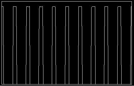
Using the MZ A-D converter - a quick trial, looking at the 32 kHz from a RTC chip and displaying in TeraTerm -  It shows about ten cycles of 32 kHz, ie about a third of a millisecond, using 256 points, which points to about 3 x 1000 x 256 = ca 750000 measurements/sec. (12 bits too..good stuff !!) It is taking a short cut though  , ie no USB. To synchronize with the USB , ie no USB. To synchronize with the USB maintenance will be quite involved so that will have to wait for a while. (ed) The "zadacq" routine is just a loop getting measurements and loading the array of 16-bit integers. The rest is initializing, screen, etc. eg PROGRAM sdistoburstMZ INTEGER*2 dat(256) CALL tekinit ( ) CALL tekrect ( ) CALL acquiredat ( dat ) CALL tekplot ( dat ) PRINT *, END SUBROUTINE acquiredat ( acdat ) ZADACQ acdat RETURN END ... |
||||
| isochronic Guru Joined: 21/01/2012 Location: AustraliaPosts: 689 |
BTW I have a few spare boards (they have slight cosmetic imperfection in the silkscreen), if anyone wants one PM etc. |
||||
bigmik Guru Joined: 20/06/2011 Location: AustraliaPosts: 2914 |
GDay Stu, All, I can confirm these look a very nice board (I have 2 but yet to build them) I think that this board could benefit from a daughter board to bring out suitable headers for various connectors, for example a 40 pin header for the 5"/7" displays and a 14pin for the SPI displays. As well as ps2 connectors etc. Do you have plans for such a board? I am considering doing one for it but I do not want to step on your toes if you have plans for such a board.. As I have mentioned before I have been looking at a MuP 100 but I wasn't able to fit all I wanted into a 50 x 50 board ( I was over confident and too cocky I think .. It. Just will not fit ) . What do you think Stu? Regards, Mick Mick's uMite Stuff can be found >>> HERE (Kindly hosted by Dontronics) <<< |
||||
| isochronic Guru Joined: 21/01/2012 Location: AustraliaPosts: 689 |
That's a good idea, it would give flexibility too. My interest is mainly the analog side - the MZ A/D converter is phenomenal. I am looking at the analog setup to try to decide which to use.. it looks like there are 5 dedicated A/D converters accessing a few pins each, and another shared that is more spread out. I am thinking of a small shielded analog board with buffers/opamps etc, but that would be separate from digital. It would be good to keep port B and the PMD ports as complete sets. Apart from that I haven't progressed the digital i/o side at all (and haven't keep up with the info needed), if you do that it would be great  . Have a bash ! . Have a bash ! |
||||
bigmik Guru Joined: 20/06/2011 Location: AustraliaPosts: 2914 |
GDay Stu, I might just do that.. I think, at least at this stage, it might be the best approach for me to do a daughter board for the sn-7x. Kind Regards, Mick Mick's uMite Stuff can be found >>> HERE (Kindly hosted by Dontronics) <<< |
||||
| isochronic Guru Joined: 21/01/2012 Location: AustraliaPosts: 689 |
To float an idea, it would be good maybe to put multiple-I2Cs and/or SD adapters on a active buffer card which could then use spi for a fast burst transfer to the main board? I had been toying with the use of (sound of being dragged over broken glass) an arduino variant, but I guess a micromite would be well suited as well (?) edit - in other words, splitting the processor function from the anciliaries. Eg A "fast bridge" would handle fast digital io like lcd updates, and a "slow bridge" to collate the slow i2c and sd card data flow in buffers. |
||||
| isochronic Guru Joined: 21/01/2012 Location: AustraliaPosts: 689 |
I have been asked if the usb-serial connection can use a pic1455 instead of a mcp2221a - I *think* the mcp2221a is based on a pic16f1455 or very similar, with proprietary microchip code running on it. The price is very similar. So, as far as the serial comms are concerned, it should be OK. As an experiment I built one of Micks Mup3, (not bad Mick!) using a 1455 (and with software that usually ran via a mcp220/2221) and it seems ok. There is a difference in that the 1455 serial -> pic line seems to default to low at least until comms establish, whereas other chips ('2221a, etc) set it high as a default. The main difference is, the '2221a does not have the programming code. Personally I think a finished reliable pcb should not require reprogramming routinely, it is like building a Ferrari and then adding an engine crane to it so the engine can be replaced easily !! |
||||
| WhiteWizzard Guru Joined: 05/04/2013 Location: United KingdomPosts: 2817 |
Oh, a bit like this you mean . . .   For everything Micromite visit micromite.org Direct Email: whitewizzard@micromite.o |
||||
| Page 1 of 2 |
|||||