
|

|
Forum Index : Electronics : Simple battery charger
| Page 1 of 5 |
|||||
| Author | Message | ||||
| SpmP Newbie Joined: 10/10/2010 Location: New ZealandPosts: 32 |
A friend of mine far out in the country gave me a really interesting design brief and set of projects: The brief is: Must last 20 years.
Must be made from standard, scavengable parts. Must be user serviceable, so simple and understandable. The basic project is a controller to turn on and off a battery charger to make sure the batteries never die, and a solar shunt controller. I present here my super simple solution to the battery charger relay, with PCB layout. The circuit works remarkably well, despite its simplicity. More smarts would be good, but given the brief this is sufficient. Circuit and PCB layout (ish) is attached. The circuit it for 12V ATM, but should be easily modifieable for other voltages. 48V would require a different regulator, so hence a diferent circuit to accomodate an LM7805, so maybee need to add a cutable trace for an extra resistor in the return... 
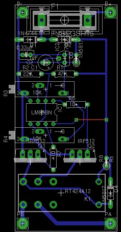
For the solar shunt controller I was going to simply build them a Ghurd controller but this fails in the standard parts category, and as there is still some room on the PCB figured I could go to a quad opamp and use the same high reference point (VrefHigh lets say). As the hysteresis is fixed I figured it wouldn't be too hard to do with a single vref and opamp... but I suck, and all attempts (in LTSpice) to mak the multitude of circuits available on the internet to work failed... I am after a hysteresis in the order 0.1V.... Help suggestions and feedback are welcomed! Its a super fun brief that has got me from designing impossible to impliment thing, to in a week having circuit that work! Wow maybee I can start using my solar panels 8) Cheers Jasper |
||||
| Gizmo Admin Group Joined: 05/06/2004 Location: AustraliaPosts: 5078 |
Hi Jasper Yeah its a good idea to stick with standard components for something that has to last that long. Far to often we have to throw something away because it uses a microcontroller or speciality IC that cant be replaced. These days you have more chance of fixing a 30 year old item than a 10 year old item. Instead of a LM358, could you use a quad op-amp IC? That would give you an extra two op-amps for your shunt regulator. The circuit is hard to read, because the forum software resized it down. Tip: The forum resizes JPG images to 500 pixels wide, fine for photos, but not for detailed drawings. For those, save your drawing/circuit as a GIF file and upload it, the forum resizes GIF's to 1000 pixels wide. The idea is 1000 pixels should be big enough for that sort of detailed image. Glenn The best time to plant a tree was twenty years ago, the second best time is right now. JAQ |
||||
| SpmP Newbie Joined: 10/10/2010 Location: New ZealandPosts: 32 |
Yep, thats the idea. I talked to Len, and he said he may have a simple solution for fixed hysteresis using one opamp. I thought I had said that I would go to an LM348, but yea... tis the idea. I still have to find the standard device that has a scavengable one. But I figure if I use a really really standard opamp, then any more modern version would be a big improvement. Len said something about being better if it was rail to rail opamp, a distinction I do not understand and he can hopefully shed some light on. Here is the image as a gif. I am also interested to know if there are any gotchas in this circuit that may see it dying an untimely death. 
Cheers Jasper |
||||
| larny Guru Joined: 31/10/2011 Location: AustraliaPosts: 346 |
Jasper, We can simplify the circuit somewhat. The Hystersis can be done with one Op Amp. Hence Q2 etc. won't be necessary. Firstly, I have derived the formulas for your info. They should give you some insight into using an Op Amp as a Schmitt Trigger. I have not included every step in the maths, (I tend to do a lot in my head). So if you have any questions, just ask. I'll post the circuit showing how I would do it later. Len 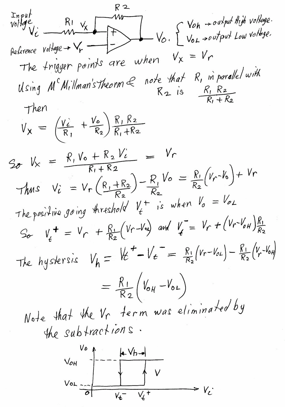
|
||||
| Gizmo Admin Group Joined: 05/06/2004 Location: AustraliaPosts: 5078 |
Yeah Len's right, you can do it with just one op-amp and a little bit of feedback. I've built something similar in the past, using trimpots for R1 and R2, which isn't a good idea  , when you adjust one trimpot it affects the other, so you need to go back and forth making little adjustments to each trimpot until you get it right. Its smarter to do the maths and used fixed resistors, with maybe a single trimpot in series with R1 to get fine adjustment. , when you adjust one trimpot it affects the other, so you need to go back and forth making little adjustments to each trimpot until you get it right. Its smarter to do the maths and used fixed resistors, with maybe a single trimpot in series with R1 to get fine adjustment.
You could ditch D3, its only there to protect the 7805 from reverse current, but not really needed in your circuit. Also ditch D1. Its there to blow the fuse if the power is conneced back to front, but the circuit is protected by D2 anyway, so no point in blowing the fuse. In fact we dont really need the voltage regulator at all, a simple op-amp with feedback will work, but I'll wait to see what Len comes up with, he's the man when it comes to this sort of stuff. Glenn The best time to plant a tree was twenty years ago, the second best time is right now. JAQ |
||||
| SpmP Newbie Joined: 10/10/2010 Location: New ZealandPosts: 32 |
Hmm Len, Reminds me of my old electrotech days... Except that I have never come across McMillmans theorem, and the only web references are you on another forum... So in terms of the derivation (and yes I admit total ignorance!), What is McMillmans theorem And, if they are different questions why is R1//R2? In terms of my circuit, this has a major limitation, which may not be too big a deal, but it is that Vh is proportional to VoH... which in my case varies anywhere from 10-15V I thought about running the opamps off a linear reg, but would need to further reduce the voltage on my divider, such that ViHigh < 5v in the case of a 7805, with 5v being necessary due to the dropout at the 10V side of things... so let me see... Ignorance forces me to assume that VoL is gnd/0V actually do the calc: Vh@15V = 0.1V R1/R2=6.66e-3 Using Above R1/R2 Vh@14.4V = 0.096 Vh@13.8V = 0.092 Vh@13.38 = 0.82 hmm shouldn't really be a problem. Probably better to set it at 0.1 for 13.8V for example, and have it a little higher for the 14.4/15V range. I guess T&E will tell. In terms of R1/2 values, R1=1k and R2=150K for example, is this the correct order of magnitude? Now, please talk me out of using a quad opamp... It seems to me that in terms of the battery charger controller side, being able to set Vh and Vl on a 15turn pot is a good thing, with them being independent and all... In terms of using one opamp and a hysteresis with feedback I would need the opposite direction around the loop, and then the low point wouldn't be a set point, rather a differential. Would this low point be hard to measure? For example, assuming that I can get the hysteresis loop to go the other way, I get my variable voltage supply, turn my hysteresis pot to minimum, then set my supply to the Vh I want to achieve, then reduce the supply until the relay clicks in, and iteratively set the hysteresis taking into account that it is getting smaller as Vin decreases.... This to me doesn't seem nice, or reliable for big differential differences.... please correct me if I am wrong. 8) Great thanks! Jasper |
||||
| SpmP Newbie Joined: 10/10/2010 Location: New ZealandPosts: 32 |
Heya Gizmo, It will be interesting to see what comes from this... omg ignorance is a form of bliss 8) D1 is a 15V zener to protect the circuit in case the voltage spikes too high for too long, or is connected to a 24V supply etc. edit... you are absolutely right about the 7805 protection diode being unnecessary. Thanks |
||||
| larny Guru Joined: 31/10/2011 Location: AustraliaPosts: 346 |
Here is the general form of McMillman's theorm. My recollection is that it can derived by using the Superposition Theorm. It is very useful. I use it often. Another useful theorm is Thevenin's Theorm. Glenn, Yes, I intend to make the trigger level & hystersis adjustments as independent as possible - I may have to compromise in order to keep the circuit simple, we'll see. Len 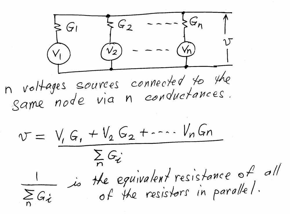
|
||||
| larny Guru Joined: 31/10/2011 Location: AustraliaPosts: 346 |
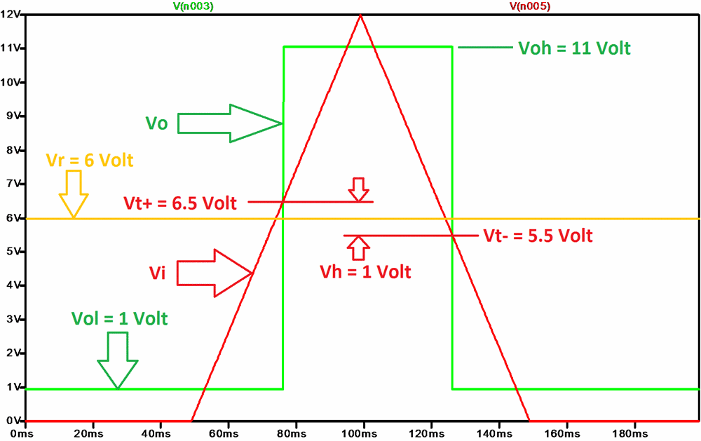
Jasper, I'll consider the questions in your long post later. Here is a simulation I did using LTSpice. As you will see, the levels & hystersis are according to my formula. Now, note (in my formula) that Vh is independent of Vr. I suggest you check this by changing Vr in the simulation. The Voh & Vol issue is the reason why I suggested a R2R Op Amp. It can also be avoided by using a Comparitor since the output is an open collector transistor, so it switches from Vsat to Vcc. Len 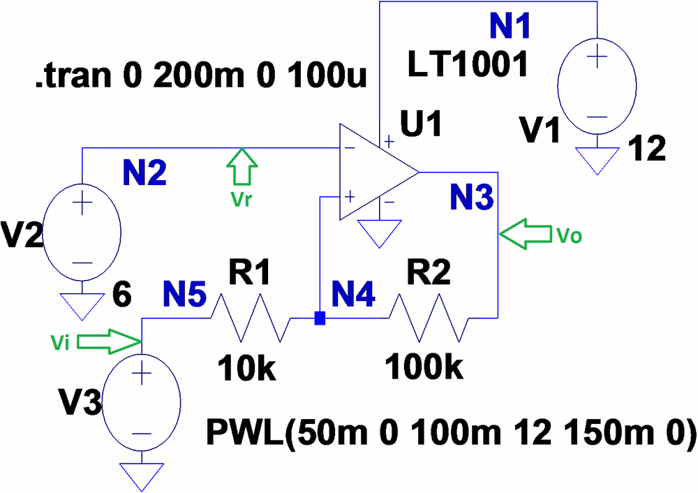
|
||||
| SpmP Newbie Joined: 10/10/2010 Location: New ZealandPosts: 32 |
Heya Len, Thanks for McMillmans theorem, makes sense now. The single opamp with vref works brilliantly with Vh ~ 0.1V, but when Vref and Vin are reversed (to change the direction) and a hysteresis of say 4.4V it doenst look quite so flash in LTSpice, with high point trigger drifting down as hysteresis increases. Gardam my math brain is rusty... trying to R2 such (assuming 1K R1) st. desired hysteresis is achieved, seeing as Vh changes with Vin. Should be simple. Common math brain! (Or maybee spice is taking other things into account) edit: was writing this as you were writing that... will read above first. hold edit again: Just to reiterate I set Vi=VoH, or should it be Vi=Voh-0.85 as opamp gets supply from Vin |
||||
| larny Guru Joined: 31/10/2011 Location: AustraliaPosts: 346 |
Jasper, Did you see my previous post with the ST simulation? You said above that you want the relay to operate when Vin is reducing. Is this correct? I have been assuming that you would want the relay to release as Vin decreases. It does not make any real difference, it is simply a matter of using either a Non Inverting ST (as per the maths I posted & in the simulation) or an Inverting ST. I can post the maths of that also if you wish. I'll now look at your next post. Len |
||||
| larny Guru Joined: 31/10/2011 Location: AustraliaPosts: 346 |
Here is the maths for the inverting ST. I suggest you check it with a simulation as I have not done so. Again, Vh is independent of Vr; & therein lies a clue. I'll leave you to check & ponder. Len 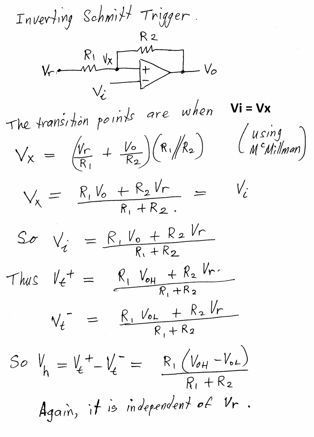
|
||||
| SpmP Newbie Joined: 10/10/2010 Location: New ZealandPosts: 32 |
Good Day Len Thanks for the above. I have not gone through the math thus far, but have been playing with spice and the real thing to see if I can get both parts of my circuit working using only hysteresis, with the following issues: Before I pulled apart the breadboard circuit as per the schematic posted, I thouht I would look at what happens if I fed the LM348 with the 5V supply from the lin. reg to keep VoH stable (4V, the 0.85v was the voltage drop from Vcc to VoH for lm342). The circuit fundamentally failed to work. strange. Anyway, for the non inverting feedback with 0.1V hysteresis, with Vi from a voltage divider, I found that the voltage devider resistors had to be at least an order of magnitude below R2. So with Voltage divider of 10K and 5K, and R1=10K, R2=660K it all worked quite nicely. Of course the 0.1V hysteresis becomes 0.0333V... so really need R2=1M, havnt tried that yet... BUT with the inverting circuit and a hysteresis of 4V lets say, it was a giant nightmare even in spice, but eventually got close to working. I was aiming to use the same Vref for both the inverting and non inverting schmitt trigers, and the same voltage divider... Unfortunatly combining them both does not work as yet, with different Vrefs needed it seems. I still feel like for the 4v hysteresis, my original circuit is more intuitive to setup and understand. I was aiming at supplying the opamps with the 5v to keep VoH stable, rather than use dual zeners. ...right goto sort out oscillations on my solar hotwater level sensor... damn thing.. resistor divider across water... PITA |
||||
| larny Guru Joined: 31/10/2011 Location: AustraliaPosts: 346 |
Jasper, I can't follow what ypou are saying above. A picture is worth a 1000 words. Len |
||||
| SpmP Newbie Joined: 10/10/2010 Location: New ZealandPosts: 32 |
Ok Len, What the above amounts to is that the attached circuit does not work. I have included the LTSpice files with combined and separate circuits if that makes it clearer what I have tried. THe circuit fails in that the one setpoint cannot be used for both, and that the 4v hysteresis schmitt trigger seems very sensitive, and hard to set. After playing with it a bit today I am thinking I may still have to use the original circuit for the 4v hysteresis part (battery charge relay) and the schmitt trigger for the solar shunt controller, but probably with a separate resistor divider for both... 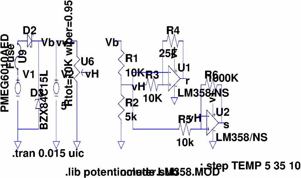
Oh dear, the image is a mess 2012-05-01_200509_battery-relay_solar-shunt_control.zip How did you add all the nice lines and arrows to your LTSpice plot please? |
||||
| larny Guru Joined: 31/10/2011 Location: AustraliaPosts: 346 |
Jasper, You know a lot more about LTSPice than I do. I don't have the Pot option & don't know how to load it. I just use resistors & change them as necessary. This is how it came up on my LTSpice. Len 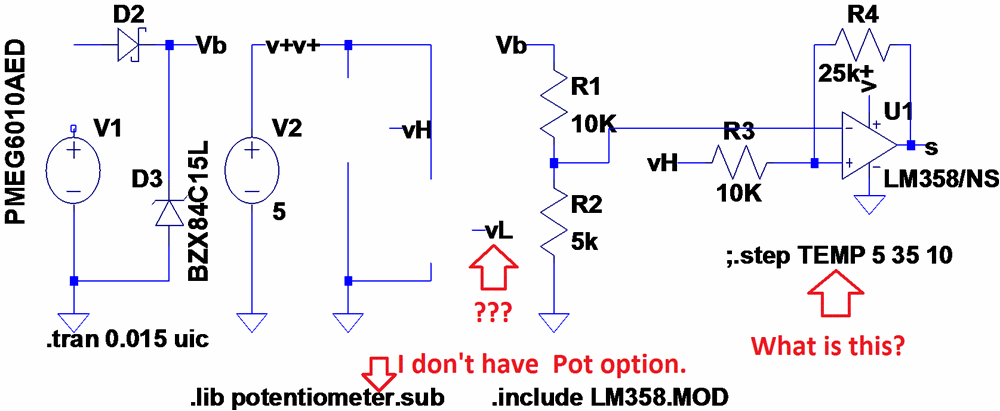
|
||||
| larny Guru Joined: 31/10/2011 Location: AustraliaPosts: 346 |
I tried to run your simulation, but I don't have the potentiometer.sub or the LM358 model. I noticed that you provided them in your zip file, but I don't know how to load them. Some weeks ago I downloaded the potentiometer.sub file tried to load it, but it did not work. So I tried deleting the exotics in your simulation one by one but each time I tried to save, I received this error message:- 
Even when I eliminated all of the exotics (see below), it still did not work. In some tuition in how to load models, etc. would be appreciated please. Len 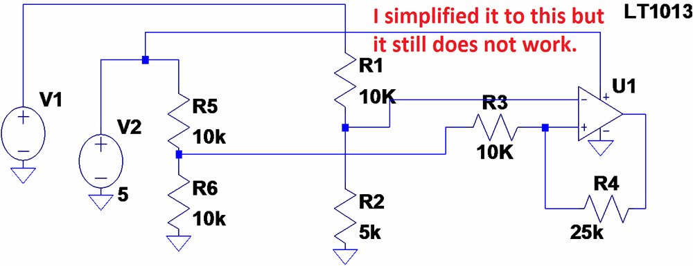
|
||||
| SpmP Newbie Joined: 10/10/2010 Location: New ZealandPosts: 32 |
Sorry for the long delay in replying My bad there is lots missing. Firstly, Adding parts: In LTSpice there are two parts to a ... part. a) The spice bit, the .lib and .sub files. These live in LTspice/lib/sub LTspice will most likely be in: C://Programme Files/LTC/LTspice... b) The symbol, the picture that appears in the schematic. These .asc files live in various folders in LTspice/lib/sym I have made a folder in LTspice/lib/sym named User Added where I place all my symbols so they are unaffected by upgrades. There are subcircuit things as well, and I find using them to be a PITA as I dont fully understand them yet. In terms of the attached circuit, the symbol file for the opamp is opamp2.asy should be located at lib/sym/Opamps/ put potentiometer.sub into LTspice/lib/sub The step function is quite useful, currently it is commented out with the semicolon, but basically it steps through a component value or whatever with three values, start stop step. This is a special case where it will step through changing the temperature from 5 to 35 degrees in 10 degree jumps. So for another example, for a resistor, change its value to {RBLAH} then with the step spice directive, add: .step param RBLAH 10k 20k 1K There are other types of steps... got run for now another spice directive when you hve done this is: .param RBLAH 10K sets the value again.... vL is not needed. |
||||
| larny Guru Joined: 31/10/2011 Location: AustraliaPosts: 346 |
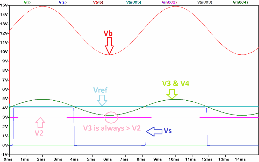
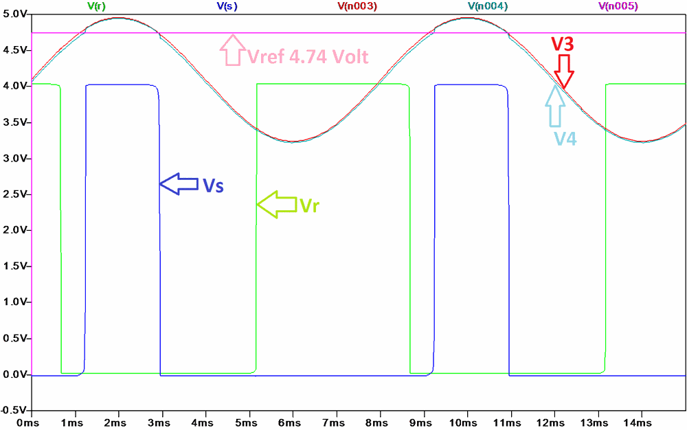
Jasper, Thanks for the assistance, I loaded the opamp and potentiometer files. The opamp appears to be working, but the potentiometer file was not found. So I simulated it using 2 resistors as you will see below. The design process I follow is roughly as follows:- 1. Draw the configuration. 2. Do the maths. 3. Do the calculations in Excel, or for simple circuits I just use a calculator. 4. Then, if necessary, I do a simulation using LT spice. 5. Build and test. There are often some iterations in the process. You appear to have jumped over steps 2 & 3. The maths and the calculations essentially show you how it works and how to set it up. I have been thinking about how I would do it. There are several options, so I'll Post them in a day or two. The attachments below show why the r output is not changing. The signal at N3 never passes through the N2 voltage. I don't know how you inserted the r & s designations for nodes, so I had to use the node numbers. In my next post, I will include a modified version of your circuit that will work the way I think you want. Len 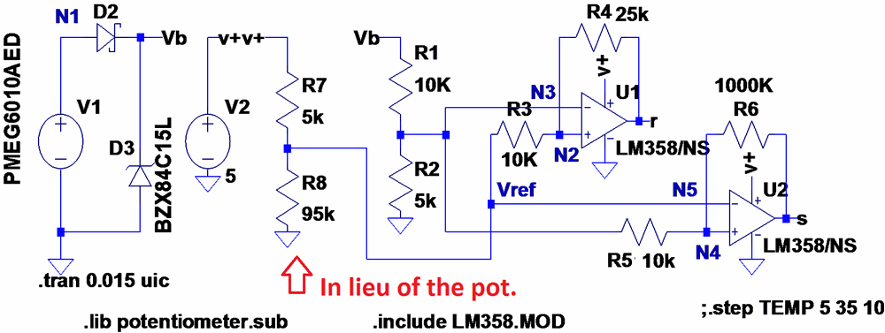
|
||||
| larny Guru Joined: 31/10/2011 Location: AustraliaPosts: 346 |
Jasper, I discovered why the r output was not working. In my version of your sim, I set R7 and R8 to 5k & 95k respectively in order to simulate a 100k "pot" set at 95%. Your problem was that R3 & R4 were loading the reference voltage Vref down from 4.75 Volt (as it should have been) to about 4.2 Volt. So I changed it to a 1k "pot" and this solved the issue. However, I'll make some improvements & show you what I have done in the next post. Len 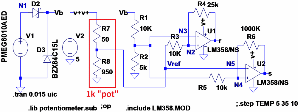
|
||||
| Page 1 of 5 |
|||||