
|

|
Forum Index : Electronics : Trouble_Oatley-K220 Regulator
| Page 1 of 2 |
|||||
| Author | Message | ||||
Gill Senior Member Joined: 11/11/2006 Location: AustraliaPosts: 669 |
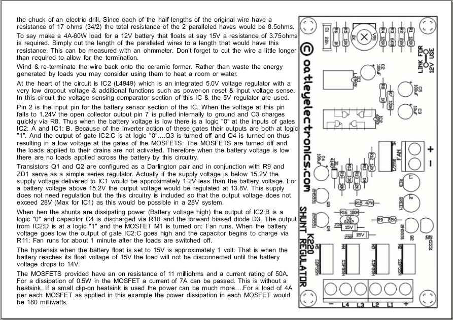
I'm having trouble with my Oatley K220 shunt regulator. There is suppose to be 1v hysterisis between divert and charge but there is none, such that my load (lights) are on an off like a bloody Christmas tree. The circuit description does not detail what provides the hysterisis, and I see no positive feedback circuit that I can identify. Any thoughts? Can anyone help? 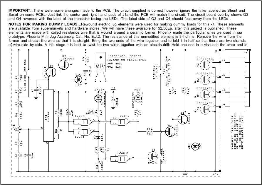
 was working fine... til the smoke got out. Cheers Gill _Cairns, FNQ |
||||
| Gizmo Admin Group Joined: 05/06/2004 Location: AustraliaPosts: 5078 |
Hi Gill The more I look at that circuit, the less it makes sense. I dont understand why they have designed it the way they did. Q1, Q2 and ZD1 could be replaced with a simple 7815 reg for a start. And the L4949 is only used as a 5v regulator and op amp, waste of an IC. 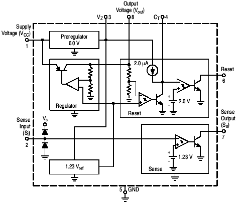
And no, I cant find any hysterisis either. There would be some in the op amp within the L4949, but only a little and you have no control over that. There is a small delay, thanks to C3. This circuit looks like someone had a few extra components they wanted to use for the sake of it, but it could have been designed with a lot less. I would try a 10k pot with 22k series resistor between pins 2 and 7 of the L4949. The will provide some feedback, you may have to play around with the values a bit. It is possible that this circuit runs more as pulse width modulation into the dump load, so its will switch the dummy load off and on quickly to pull down the battery voltage, and this would flash your lamps like a christmass tree 
Glenn The best time to plant a tree was twenty years ago, the second best time is right now. JAQ |
||||
| RossW Guru Joined: 25/02/2006 Location: AustraliaPosts: 495 |
Can say that for most of the controllers I've seen! Well, not really. It would be ok for a 12V system, but a 24V would go very close to exceeding the max input of those 78xx series regulators, and 36 or 48V systems would be right out. Indeed. I knocked up a little circuit for the guys in the IRC channels. Several have built it now, and have had good results. It's a really simple beast, can be made out of junk-box parts....  |
||||
| Pt w/field Matt Senior Member Joined: 24/02/2006 Location: AustraliaPosts: 105 |
hi Gill check out s/chip august 05 for 220 mods, lots of resistor changes matt down south |
||||
Gill Senior Member Joined: 11/11/2006 Location: AustraliaPosts: 669 |
Thanks fellas for the replies. Glenn, Your suggestion of adding a feedback circuit was what i was thinking of too, and as it is the simplest/quickest to impliment, I'll give it a go first. Ta. Ross, Thanks for the comments. I like your circuit, at least I can understand it, and that gives it an edge come the day it needs repair. So often the simple things in life are best. You say your guys have had good results with it so I have filed it for quick access for next time. Matt, Have downloaded those Notes & Errata you refered to and have started to modify mine as the lack of adjustment range applied to mine. Thanks As a further frustration the Notes & Errata cite reducing hysterisis voltage(on 24V)by adding a zenner to the voltage devider. If anyone can explain this to me, please do. I just don't get it. 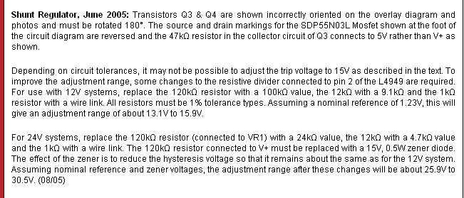
Has anyone else had troubles with this K220 kit or the K241 kit? Was thinking of going to the K241 as I felt it would be an individual mill reg in a multi mill enviroment. Besides the single reg for a multi input system(all eggs in one basket), are there other options? was working fine... til the smoke got out. Cheers Gill _Cairns, FNQ |
||||
Bryan1 Guru Joined: 22/02/2006 Location: AustraliaPosts: 1344 |
Hiya Gill, I've got one of those K220 shunt regulators on my nife battery bank. It's setup for 16 volts simply by changing some resistors and I've had it working for ages. I did notice on mine when it switched over it hunts back and forth, but with my dumpload being nearly 5 amps the current draw will bring down the battery voltage pretty quick. I made up the shunt regulator that Ross designed and put the pic in here and mine is setup for 24 volts. The first one is on verobaord and the second one I designed and made a pcb for it. Now for such a simple circuit that can be made from those electronic bits in that shoebox I reckon its as good as some commercial ones costing $$$. So my advise is just put up with the hunting on the K220 and get busy and make that shunt regulator Ross kindly shared with us. Cheers Bryan  |
||||
Gill Senior Member Joined: 11/11/2006 Location: AustraliaPosts: 669 |
Great endorsment of Ross'circuit there Brian. As for the K220, you say yours is hunting too. I guess it's not annoying when used with a heat load dump. I'm starting to wonder that though they said hysterisis they really meant time delay. Though they were specific in saying 1 volt and not 1 second. In any case "Where there's a Gill there's a Way" I have 3 of those K220 shunt regulators and the Scott in me won't let me waste those precious $ spent. I've added a feedback circuit, as per Glenn's suggestion, though am finding a total of 120K to 150K ohms gives the 1 Volt hysterisis I desire. Still a job in progress though. Will advise final values for those interested. was working fine... til the smoke got out. Cheers Gill _Cairns, FNQ |
||||
| Highlander Senior Member Joined: 03/10/2006 Location: AustraliaPosts: 266 |
Hey gill, how did you go with your mods? I run rewound elements on mine. I watched them closely and with 35.3 amp dump on 1760ah bank, the voltage dropped .2V before starting to charge again. Anyway if your still dirty on the 220 I'll buy them off you as they are discontinued. Thanks with the wiring help, the fets are off the board. 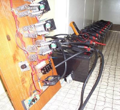
by the way do you know what this part is? It's off a small charger. I had a 240ac gen going for something else and I hooked it up but it crapped out, it looks like a resistor but with no bands, just grey (240ac). I think I'll stick to the 12v gen next time. 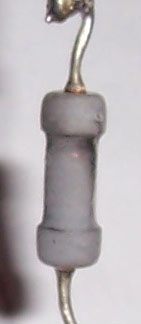 Central Victorian highlands |
||||
Gill Senior Member Joined: 11/11/2006 Location: AustraliaPosts: 669 |
G'day Highlander, Glad to hear one of us is making some headway. That mod has had to take a much lower priority rating, though did do a little more. I'm running a 330k resistor for feedback (pin7 to pin2) but still not 1v. I get .6v and as I get so much variation what with the dump load plus all the other loads from goodies as required, I've resigned to accept an amount of on/off with the load dump lights. Do intend trying again soon(got right range of resistors now). Bit of a ring-in that resistor.  It makes me think of one I had to replace in a battery drill charger the other day. All blackened it was guess work reading the colour bands. Very low resistance it was current limiting. Ended up cheating, -borrowed a second charger that worked and looked inside when no one was watching. It makes me think of one I had to replace in a battery drill charger the other day. All blackened it was guess work reading the colour bands. Very low resistance it was current limiting. Ended up cheating, -borrowed a second charger that worked and looked inside when no one was watching.
Bet your missus loves that load dump. I see howling cold Victorian winds, glowing elements and a comfy deck chair. What a life!? was working fine... til the smoke got out. Cheers Gill _Cairns, FNQ |
||||
| herbnz Senior Member Joined: 18/02/2007 Location: New ZealandPosts: 258 |
Hi Something to throw in the melting pot Re load dumps. I have given up on regulators particuarly the type that attempt to balance the incomming to maintain battery condition. Nowdays I use a dump on the AC side of the inverter that is a standard hot water element in the cylinder usually only 1500 or 1000 watts though. this is controlled via a smart relay that is sensing the battery voltage I use a relay but solid state ie triac's could be used. Doing this allows me to program all sort clever features via my computer ie three stage charging,adjustable on time for dump, twin battery change over, alarms to my cellphone,etc even then on the cheapest unit i have 3 outputs 8 inputs for future use. The idea hits the battery hard for say 10 sec usually lowering voltage signifigantly then after 10sec stays of until they recover, much better for all connections rather than small currents that corrode connections including those internal in the battery. I have used Zeilo brand but many others on marked and as mass produced usually much cheaper than conventional regulators. I do have a emergancy shut down senser on DC side that is triggered with a simple cct for over voltage never needed to this day about 5 years now. Cheers Herb |
||||
Gill Senior Member Joined: 11/11/2006 Location: AustraliaPosts: 669 |
G'day Herb, Thanks for that. It's an idea I suppose all of us have toyed with, that is, rather than Dump the excess into some wasteful load, to use it for a more practical purpose. Most practical purposes being 240ac based? I don't know about that. In any case you are still sensing the battery voltage and turning on a switch/s when it exceeds a certain point/s. So it's still a regulator. Though a smart one by what you say. Are you controlling it through the computer directly, or is the computer programming a chip like a Picaxe? The 3 stage load dump is interesting. Rather than me ask questions, perhaps you could give us more details. Perhaps a circuit and a pic of that Zeilo device would be great too. My origional idea was to use three Oatley_K220 regulators in parallel with each turning on a smallish load dump. Each regulator set at progressively higher voltages thus achieving a dumb-mans taper off or stepping regulator. 3 in parallel also served as a fail safe should one fail. But as this thread indicates, performance was not as predicted. So I'm stuck with a "bang-bang" regulator (BANG it's all ON - BANG it's all OFF). Not the best for an expensive battery bank that I expect to last. I'm waiting for the smart bunnies to come up with a PICAXE stepping regulator as I have only just discovered the chip myself. So many possabilities...... was working fine... til the smoke got out. Cheers Gill _Cairns, FNQ |
||||
| RossW Guru Joined: 25/02/2006 Location: AustraliaPosts: 495 |
I've mentioned this several times in the IRC channels, but not here. If you have a dumpload controller, even if it only has the FET output, have you considered using the fet to merely control a double-pole relay, and switch your *3 PHASE* load directly across the wind generator - *BEFORE* the rectifier? This means you won't be over-stessing your rectifier, or being so hard on your batteries. When your batteries get up to volts, rather than sucking them down, *dissipate the windgen power* to stop any more going into your batteries? Doesn't really matter then if it's "bang/bang" switchig, it's not hurting the batteries or the rectifier. Just a thunk. |
||||
Gill Senior Member Joined: 11/11/2006 Location: AustraliaPosts: 669 |
G'day Ross, I see aspects of your suggestion that has merit, though I can't see that cutting off the power in one hit, be it fet control before the rectifier, or regulator control, or a knife switch at the battery terminals, will stop 'bang-bang' a full current rush into the batteries when the switching occurs. Perhaps I miss something? In fact I see the rectifiers being more stressed as with the standard regulator the current is merely diverted and not shocked with full current On's and OFF's. (Most light bulbs blow at turn on.) Of course I'm not saying that's a reason to stop using light bulbs or pre-rectifier control it is merely a consideration. I think another consideration besides full current shock, is that high currents cause gassing and heating, up to the point where the regulator bangs the power off (or divert). My batteries seem to do this as they approach full charge. I believe tapering off the current reduces this effect. I understand the trend today is towards pulse width control as the best way of tapering off charge and prolonging battery life. Certainly the solar commercial trend is that way towards battery care. Step switching being the in between of PWM and Bang/Bang. What I'd like to see is your regulator (posted above), modified, say built around a quad op-amp/comparator, to give a 3 step voltage control of 3xload dumps. Something DIY in the backshed? 
was working fine... til the smoke got out. Cheers Gill _Cairns, FNQ |
||||
| herbnz Senior Member Joined: 18/02/2007 Location: New ZealandPosts: 258 |
Hi Gill The smart relays are same as pixaxe but built up units outputs inputs etc. I have tried to include a couple photos one of unit one of type prog u use this is a three stage dump gives 10sec bursts into my water heater. I see large bursts are much better on batteries than pussy footing around, small currents corrode connections. Gasing of baterries must occur at anything above 85% charge. I have no fear of damaging batteries with this style charging quite the converse. The time I have damaged batteries is the use of smart drive at high rpm on my hydro the high frequency ripple removes all sulphating but then shakes them to destruction. I always use a filter now with smart drives. Back subject if any interest in the smart relays i will try to get better copy of my program but most ppl can work something out must be 101 ways doing it. 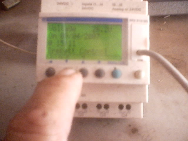 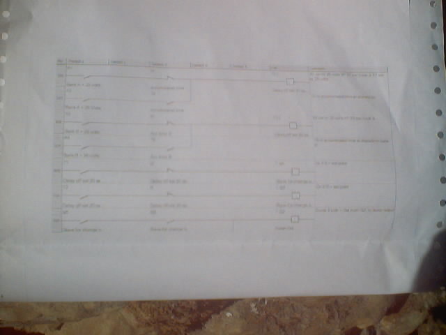
Cheers Herb |
||||
Gill Senior Member Joined: 11/11/2006 Location: AustraliaPosts: 669 |
Thanks Herb, That inspires me to keep at learning those PICAXE commands. If the chips ever arrive, & if I live that long, In time I'll make one of those.  was working fine... til the smoke got out. Cheers Gill _Cairns, FNQ |
||||
| martinjsto Senior Member Joined: 09/10/2007 Location: AustraliaPosts: 149 |
can anyone tell me the best n-power fet used in ross design seems there is a lot of them to choose from thanks martin free power for all McAlinden WA |
||||
Gill Senior Member Joined: 11/11/2006 Location: AustraliaPosts: 669 |
G'day Martin, Unfortunately, No. However, making a few assumptions and taking a stab at your battery and generator, I'll suggest Tricky Dickies cat Z 1853 SSP60N06 N-Ch 60V 60A switch MOSFET $4.97 as being generally suitable and available to most people. was working fine... til the smoke got out. Cheers Gill _Cairns, FNQ |
||||
| martinjsto Senior Member Joined: 09/10/2007 Location: AustraliaPosts: 149 |
thanks gill, i will get one tomorow and fit it to the circut, i have a few different units made now a 7p2p and a 7p1p, i also have running on my wind gens the old 3 phase star and a 3 p delta, you think a 50w 12v downlight is enough of a load? for a 12v system, i have put together a 7p1p and tested on my lathe, worked realy well except there seems to be a lot of drag when loaded with 2 50w 12v downlights, you think this is typical of these motors with that sort of load of aprox 100w? free power for all McAlinden WA |
||||
Gill Senior Member Joined: 11/11/2006 Location: AustraliaPosts: 669 |
Martin, I'm not sure what your designations mean. Is 7p2p, 7pole x 2parallel or 7phase x 2 pole and in what configuration? You've got me trying to mind read again. Regardless of what stator configuration you run, the general rule to follow is that your load dump must be equal to the maximum power output of the mill. So if your running a 12v battery, the volts at shunt regulation is generally between 14 and 15 volts so I use 15 volts. Now what is the max amps the mill puts out? Say 15 amps for a single rotor or say 30 for a dual rotor. From this we calculate the max power you're ever likely to get into the battery. Remember Ohms law where Power = Amps X Volts. So that's 15 * 15 = 225 watts Lets say 200 watts as a dump load. This = 4 x 50watt bulbs, nes par? Yes, particularly at lower wind speeds, this load is going to act like a brake when it cuts in. Just remember what it's purpose is. The dump load is there to dissipate ALL the power when the battery is fully charged. The fact that it slows the mill, well who cares, if the batteries are full and protected? If you're in a storm or a period of windy weather, that's exactly the time the batteries will charge up quickly from max amps in. You'll need max dump load then and the mill won't slow a bit in speed though it may furl. Just as a side note, you may find downlights are not very tolerant of excess voltage and 15 volts is more than they are designed for. Vehicle headlights are more suitable or do as I do and run 2paralleled x 0.47ohm 10 watt resistor in series with each downlight. Also you may find lights annoying especially at night as will turn on and off a lot. Hope that helps.  was working fine... til the smoke got out. Cheers Gill _Cairns, FNQ |
||||
| martinjsto Senior Member Joined: 09/10/2007 Location: AustraliaPosts: 149 |
thanks for the input gill the designation is from the backshed http://www.thebackshed.com/Windmill/articles/coglessFP.asp im just quoting the ones used here7p1p = 7 phase 1 pole i believe mine is a single rotor wired to the configeration on that page. i now understand the load vs rpm and the way it slows the mill when batteries are charged thanks for the clarification. i have finnished the circut above designed by ross wheeler, i have checked and checked the circut for shorts, bridges in the solder and for sceematic accuracy i did find a few errors which i fixed, i installed the cat Z 1853 SSP60N06 N-Ch 60V 60A switch MOSFET as sugested but still cannot get the 12v 50w light to turn off even with only 10v in the battery??? i am using the resistors sugested for the 12v system i purchased new caps today and installed them still same problem does anyone have any pcb made for this circuit i can purchase as im getting frustrated trying to get a simple charge controler working propely for my wind gen i built the oatley kit but had the similar problems that are stated above, i dont want to pay over $200 for one on ebay, my friend purchased one and it too failed within 3 months. i apreciate your help gill martin free power for all McAlinden WA |
||||
| Page 1 of 2 |
|||||