|

|
Forum Index : Electronics : A new controller circuit
| Page 1 of 7 |
|||||
| Author | Message | ||||
| Gizmo Admin Group Joined: 05/06/2004 Location: AustraliaPosts: 5078 |
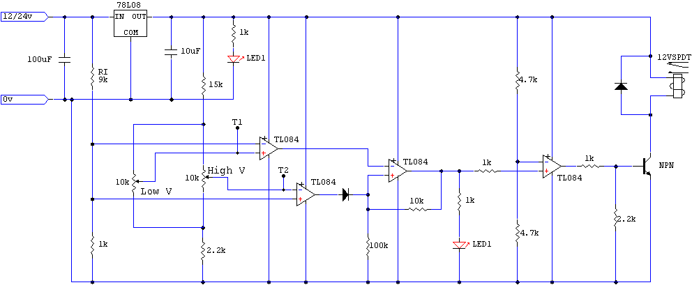
Hi guys. I'm working on a new wind/solar controller. This time I wanted something very simple, no microprocessors, and cheap. And it had to be easy to adjust. This is what I've come up with so far. Its a working circuit, tested tonight, though some values will change to get it "calibrated". 
This uses a single quad op amp IC, a handfull of other components, and a automotive relay to switch the currents. My main requirements were...
To calibrate the thing, I connect it to a 12v source, then using the test points T1 and T2, with respect to ground, I adjust the dump on and off voltage. Reading at T1 and T2 is 1/10 actual voltage. So if I want the dump load to cut in at 14.5 volts and cut out at 13 volts, I adjust T1 for 1.3v and T2 for 1.45v. Then when I actually connect it to the battery bank it will switch at the preset voltages. Unlike other op-amp based controllers I've seen, making adjustments to either trimpot wont affect the adjustment on the other trimpot. Anyone who has built a simple op-amp controller with hysteresis will know how frustrating it can be to adjust! I didnt want that with this controller. I still need to finalize some of the component values to get the T1 and T2 readings spot on, and I would like to tickle up the 7808 to supply 10 volts instead of 8, other than that its working fine. Any comments would be welcome. Glenn The best time to plant a tree was twenty years ago, the second best time is right now. JAQ |
||||
niall1 Senior Member Joined: 20/11/2008 Location: IrelandPosts: 331 |
Hi Glenn Nice work and a really neat kind of "calibration" on the op amp inputs .... 
if you get a chance i,d like to see the 48v mod ..will you you still use the 78xx in some way ? ps...if your going to tickle up that 08 to 10 i hope you,ve told it you,ll marry it first ..  niall |
||||
| GWatPE Senior Member Joined: 01/09/2006 Location: AustraliaPosts: 2127 |
HNi Glenn, this cct performs a similar function to my first dump load controller. I used a single 74c14 chip though as the amplifier. The sensing component was a logic level FET. I still have this cct working on windmills systems in remotes parts of SA. They are 24V, and the relay is a SSRelay type. This cct still really only provides voltage protection to the battery. Battery charging and maintenance is still required. Most readers would be able to make a unit like this on a breadboard. This is a another useful alternative cct to a micro. Gordon. become more energy aware |
||||
| sPuDd Senior Member Joined: 10/07/2007 Location: AustraliaPosts: 251 |
Can't argue with that. You set out goal specs and have achieved them. Nice work again Glenn 
Might I suggest you do it up as a kit for those who fear even the vero board. Should be a tiny enough PCB. I know I'm jumping the gun there as its not yet fully tested, but field beta testing is the way 
sPuDd.. It should work ...in theory |
||||
| vasi Guru Joined: 23/03/2007 Location: RomaniaPosts: 1697 |
It looks good and this is great: I'm tempted to build one  Hobbit name: Togo Toadfoot of Frogmorton Elvish name: Mablung Miriel Beyound Arduino Lang |
||||
| Gizmo Admin Group Joined: 05/06/2004 Location: AustraliaPosts: 5078 |
The controller is giving me a headache. It looks as the switching inside the op-amp isn't as clear cut as I hoped. In fact its pretty terrible, I must be doing something wrong. If I adjust T1 ( the + input of that amp ) for 1.2 volts, I thought once the voltage on the -ve input went below 1.2 volts the op-amp would switch. In fact it needs to drop to 1.14 volts before the switch happens. Thats a big offset. Same with the high side op-amp, if I set T2 ( the - input ) to 1.5, it needed about 1.57v on the +ve input before it switched state. Multiply those figures by 10 and the regulator has a inaccuracy of about 0.6 volts from the calibration made with a multimeter. Glenn The best time to plant a tree was twenty years ago, the second best time is right now. JAQ |
||||
| sPuDd Senior Member Joined: 10/07/2007 Location: AustraliaPosts: 251 |
Gizmo, is it related to the diode on the output? Or would an op-amp with closer input diff specs do it? Op-amp with offset null adjustment? Going back to analogue after MCUs is always a task. I know I'd already be considering a PICAXE, but that defeats the purpose. I have to fix the brightness control system on my old 20Mhz CRO - not looking forward to such an analogue task 
sPuDd.. It should work ...in theory |
||||
niall1 Senior Member Joined: 20/11/2008 Location: IrelandPosts: 331 |
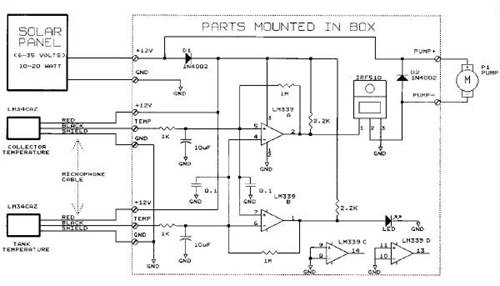
Hi glen i,m way out of my debth here but would some type of feedback on the op amps help trigger the change over points ? i read somewhere that if the change in voltage is very slow in happening an op amp can get a little lazy .. this is kind of similar (not to your specs though) off the web .. it trips in and out a pump for a solar panel (dodgy pic quality  ) )

some de- coupling caps maybe might help the inputs niall |
||||
| davef Guru Joined: 14/05/2006 Location: New ZealandPosts: 499 |
Glenn, Are you using a digital voltmeter? Perhaps even with a 10M input impedance the drop across the 15K, plus if you have the 10K pot down at the "2.2K" end of it's travel might account for the difference in voltage reading. I'd expect the op amps to switch within in millivolts, especially with max gain as you have it set up. Dave |
||||
| Gizmo Admin Group Joined: 05/06/2004 Location: AustraliaPosts: 5078 |
Thanks for the input guys. I'll have another fiddle in a couple of days. Good point Dave. When I suspected something was weird I used two digital multimeters, one on the +ve and one of the -ve, and I could measure the error. But what I didn't do was compare the multimeters against eachother! One is about 20 years old, and I wouldn't know its internal resistance. I also noticed when I was close to a switching point, touching the test point with the meter probe would cause it to trigger. I now think I need to drop the divider network resistors down in value, to increase the current a little and make them less sensitive to a high resistance multimeter. Ahh, give me software anyday! Glenn The best time to plant a tree was twenty years ago, the second best time is right now. JAQ |
||||
| sPuDd Senior Member Joined: 10/07/2007 Location: AustraliaPosts: 251 |
I think Dave may be right. A quick hit of ohms law shows tens of millivolts change with a 1Meg/V DMM. I see the chain as it stands is using less than 0.5mA. Some lower value resistors would help. Though it depends on how much of a power miser you have to be. Would a constant current source for the divider chain help? Seems to be how most analogue IC's internally keep their accuracy for reference voltages. Maybe a TL431. They seem to be the fad in most SMPSUs for keeping the opto couplers in check. Either that or buffer the measured value with more opamps? Nah... You know, we wouldn't think less of you if you whipped a PICAXE08M at that puppy 
Then again, that might just lead us back to square one with input loading. Unless you read the values to an LCD..... ahh yes, the seed is sown my dark lord 
Feel the power of the Dark Side! Whoops - I mean PICAXE... sPuDd.. It should work ...in theory |
||||
oztules Guru Joined: 26/07/2007 Location: AustraliaPosts: 1686 |
I think the voltage dividers need to be much lower impedance if your going to measure them without a high impedance buffer of some kind. I think better still to use a pwm chip (494 springs to mind here), use the internal voltage regulator for your stable reference, and then set the op amp for your on voltage, very little feedback )if any), and it will switch on the pulse train hard as a soon as trip voltage is hit. What hysteresis 
That gets rid of the second voltage setting bits, most of the parts, and the relay.... and gives a PWM output. Two fets will switch10- 20A probably (Rds .01r) without much in the way of heat sinks in that application..... happily it will do the range from 12-28v without a problem. The chip is good for over 35v. ............oztules ps I built a quick prototype last night of just this. Works well.... probably wouldn't hurt to add 4 more components and give it upper current limit to protect the fets I suppose. Village idiot...or... just another hack out of his depth |
||||
niall1 Senior Member Joined: 20/11/2008 Location: IrelandPosts: 331 |
dismembering pc power supplies is good enough therapy fun for me ( never mind getting a nice 494 ...sometimes ...and other goodies) 
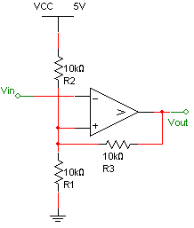
what i was trying to rembember in my last post (without the wine mist) was a schmitt trigger thingy 
bottoms up then (any excuse)....Her otto ..  .......well sort of .......well sort of niall |
||||
| Gizmo Admin Group Joined: 05/06/2004 Location: AustraliaPosts: 5078 |
Well I changed the values of the resistor divider strings to about 5k total, increasing the current and reducing the effect of the multimeter. I made no difference! Still the same problem, some sort of built in hysteresis in the opamp. Its about 0.05 to 0.08 volts past the +ve = -ve input before it switches state. I've spend too much time on this, so I'm going to give up on the "preset with a multimeter" idea. As a controller its still a good circuit, but a variable power supply is needed to adjust the thing. I really hate analogue! Glenn The best time to plant a tree was twenty years ago, the second best time is right now. JAQ |
||||
| GWatPE Senior Member Joined: 01/09/2006 Location: AustraliaPosts: 2127 |
A lot of problems with input offset errors is caused by the cct design. It is important to have the currents that enter each input of the opamp equal. I use input series resistors. There is complicated stuff inside the opamps and the operation is affected if the same current does not apppear on each input. Output loading can introduce other problems as well. This windmill controller arrangement still requires some additional components to work well with a battery. I have had poor battery performance with a single set point controller on gel type batteries. Will work with flooded systems if the electrolyte levels are checked daily, and the voltage is set high enough to gas the cells. Gordon. become more energy aware |
||||
| sPuDd Senior Member Joined: 10/07/2007 Location: AustraliaPosts: 251 |
Silly question Glenn, but did you try a different species of op-amp? Maybe the front end on that type is too fussy? Or the internal pre-bias of the output is to geared to power saving? Curse that analogue! What’s analogue ever done for us!? 
sPuDd.. It should work ...in theory |
||||
| Tinker Guru Joined: 07/11/2007 Location: AustraliaPosts: 1904 |
Well, it gave us radio and TV for half a century  Klaus |
||||
| Gizmo Admin Group Joined: 05/06/2004 Location: AustraliaPosts: 5078 |
Well I've given up on the "I could attach the controller to a battery and adjust its switching points using a multimeter, without a variable power supply." idea, its just not going to happen without a lot more development time and components. So I've modified the circuit a little, and it will need to be adjusted the old way, ie
Glenn The best time to plant a tree was twenty years ago, the second best time is right now. JAQ |
||||
| sPuDd Senior Member Joined: 10/07/2007 Location: AustraliaPosts: 251 |
Glenn, if designing this for the average person to build & setup, and the need for a variable supply bothers you - why not fit a simple LM317 and multi turn pot to the board with provision for an AC plug pack. That way all a person needs is a 12-24Vac plug pack laying about and they're set. Maybe a diode on the LM317 output to remove it from the circuit when in use. You would only need the LM317 and less than 10 other components. Perhaps just supply an LM317 based PSU as a separate option if doing a kit? sPuDd.. It should work ...in theory |
||||
| vasi Guru Joined: 23/03/2007 Location: RomaniaPosts: 1697 |
It still remain an atractive controller, easy to setup (better than what I built in past, which had histerezis). Having a variable power supply, based on LM317 at least is a must, and it was obvious for me that I had to have it before controller construction. Every construction have his own requirements and can be done step by step, not matter if we are in rush or not. So, beginners can see these requirements as normal steps. When I come in PIC programming I saw the huge diference in speed development regarding to PICAXE dev. PICAXE advantage. Is a nightmare to switch every time the serial connector of programmer, with serial connector from the breadboard, moving the power source connector from programmer to breadboard, moving the chip from montage to another place where can be programmed. And this, for every variable change. Is easy to make a mistake when you get tired. So, a development board is a must. No matter when it will be done. Is just a normal step... Hobbit name: Togo Toadfoot of Frogmorton Elvish name: Mablung Miriel Beyound Arduino Lang |
||||
| Page 1 of 7 |
|||||