|

|
Forum Index : Microcontroller and PC projects : ADC run command in MMBASIC, 8 vs 12 bits
| Page 1 of 2 |
|||||
| Author | Message | ||||
| k2backhoe Regular Member Joined: 04/12/2021 Location: United StatesPosts: 46 |
Apologies if this topic has been covered, I couldn't find it using search. As I read the documentation (5.08.00) on using the 3 ADC channels of the 2040, normal reads return a 12 bit conversion scaled to a floating point value converted to actual voltage (0 - 3.3V). Using the ADC RUN command uses ping-pong buffers to store data in two alternating arrays as packed 8-bit values. Is there any way to store the 12 bit conversion data in an array of 16 bit values? I hate throwing away the extra bits of resolution. Thanks, k2 |
||||
| phil99 Guru Joined: 11/02/2018 Location: AustraliaPosts: 2131 |
Due to a ADC hardware error in the 2040 chip the usable accuracy is about 8 bits. |
||||
| Mixtel90 Guru Joined: 05/10/2019 Location: United KingdomPosts: 6761 |
For ADC stuff the Pico 2 is supposed to meet the specification now. There is no workaround for the original Pico as it is a bug on the silicon. For simple stuff like reading a pot, light or temperature sensor the RP2040 is often adequate, especially if using a linear regulator and voltage reference to get the noise down. It's no use for precision stuff though. Mick Zilog Inside! nascom.info for Nascom & Gemini Preliminary MMBasic docs & my PCB designs |
||||
| JohnS Guru Joined: 18/11/2011 Location: United KingdomPosts: 3797 |
Er... which arrays have 16-bit values? If you're using integers in MMBasic they're 64-bit... And yes you could pack them, maybe 5 12-bits. (For 8-bit values you'd just use strings.) John |
||||
| Michal Senior Member Joined: 02/02/2022 Location: PolandPosts: 123 |
The easiest way is probably to use two characters in BCD format in a string, possibly one character and the lower 4 bits of the second one. Michal Edited 2024-11-17 04:26 by Michal |
||||
| matherp Guru Joined: 11/12/2012 Location: United KingdomPosts: 9084 |
ADC run is 8 bits for efficiency and isn't going to change |
||||
| stanleyella Guru Joined: 25/06/2022 Location: United KingdomPosts: 2109 |
would it run faster if the reads were poked to memory and read back as bytes instead of arrays as only 8 bits and you poke bytes?? |
||||
| Bleep Guru Joined: 09/01/2022 Location: United KingdomPosts: 509 |
In answer to the original poster, yes you can use 'MEMORY PACK' & 'MEMORY UNPACK', very fast, to pack 4 lots of 12/16 bit values into a 64 bit integer array, and get them back out again. |
||||
| k2backhoe Regular Member Joined: 04/12/2021 Location: United StatesPosts: 46 |
OP here. In answer to some of the replies, I am not worried about storage efficiency or packing/unpacking. I was wondering if a version of ADC RUN could store 12 bit conversions into 16 bit memory arrays in order to use the full 12 bit values. I am aware that the RP2040 is only accurate to 8 bits. The RP2350 claims to have fixed this problem, I have no evidence if this is true or not. The point is moot in either case. Matherp has said it isn't going to change and that settles it. I can do so very much already with mmbasic, I am not asking to gild the lilly. k2 |
||||
| stanleyella Guru Joined: 25/06/2022 Location: United KingdomPosts: 2109 |
I posted a simple scope prog and it sort of worked but I don't understand adc. instead of this could I dim the arrays for adc as 1 element and just get 1 sample? using 2350 usb hdmi so this will say pin in use dim c%,x%,samples!(480) SETPIN (31), AIn adc open 500000,1 'samples per second FRAMEBUFFER CREATE F FRAMEBUFFER LAYER L FRAMEBUFFER WRITE L line 119,0,119,239,,rgb(green) line 0,119,239,119,,rgb(green) FRAMEBUFFER WRITE F do adc start samples!() 'get new samples 'trigger c%=0 do:If samples!(c%) > 0.1 then if samples!(c%+1) < 0.2 then exit do inc c%:loop while c%<160 math scale samples!(),239,samples!()'scale to 240 pixel height FRAMEBUFFER COPY L,F for x%=0 to 238 'screen width line x%,samples!(x%+c%),x%+1,samples!(x%+1+c%),,rgb(magenta) 'draw new sample from sample(c%) next x% FRAMEBUFFER COPY F,N loop RUN [9] SetPin (31), AIn Error : Pin 31/GP26 is reserved on startup > Edited 2024-11-17 08:29 by stanleyella |
||||
| stanleyella Guru Joined: 25/06/2022 Location: United KingdomPosts: 2109 |
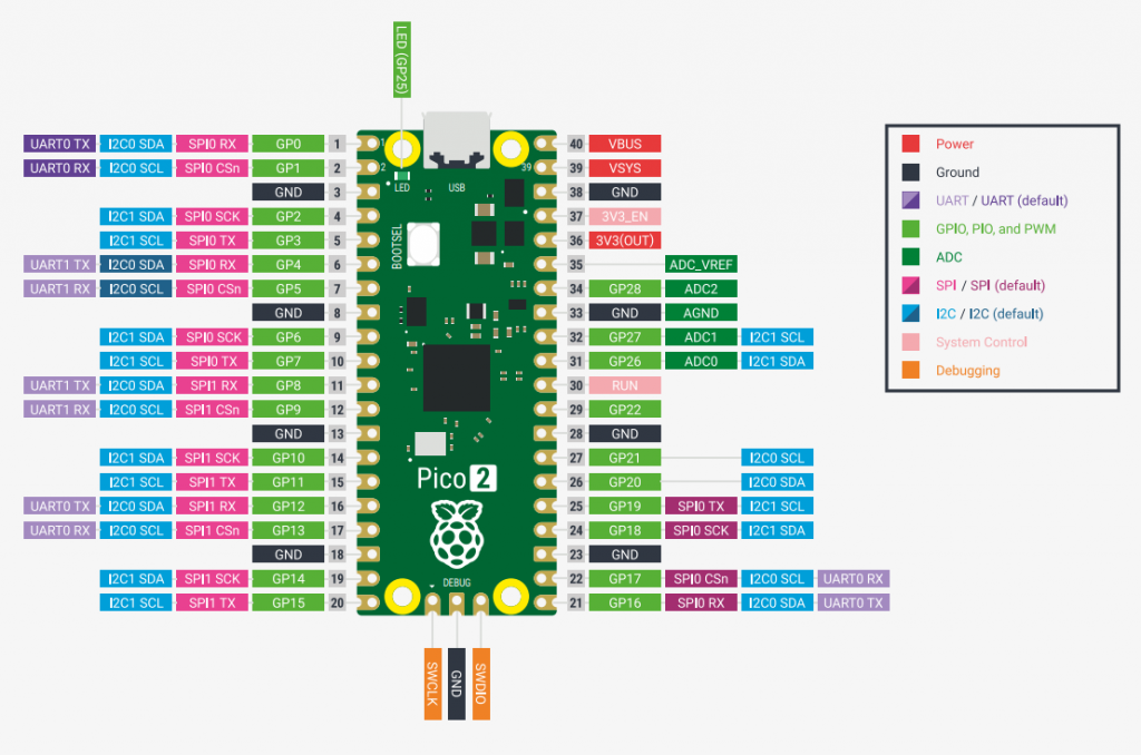
what are adc pins 2350 but on olimex hdmi? please option list PicoMiteHDMI MMBasic USB Version 6.00.00RC15 OPTION SERIAL CONSOLE COM2,GP8,GP9 OPTION FLASH SIZE 4194304 OPTION COLOURCODE ON OPTION KEYBOARD UK, 0, 0, 600, 150 OPTION CPUSPEED (KHz) 315000 OPTION DISPLAY 30, 53 OPTION HDMI PINS 1, 3, 7, 5 OPTION SDCARD GP22, GP6, GP7, GP4 OPTION AUDIO GP26,GP27', ON PWM CHANNEL 5 > |
||||
| phil99 Guru Joined: 11/02/2018 Location: AustraliaPosts: 2131 |
Try GP28 |
||||
| stanleyella Guru Joined: 25/06/2022 Location: United KingdomPosts: 2109 |
RUN [9] SetPin (28), AIn Error : Pin 28/GND is invalid >  |
||||
| phil99 Guru Joined: 11/02/2018 Location: AustraliaPosts: 2131 |
SetPin GP28, AIn or SetPin 34, AIn Edited 2024-11-17 11:33 by phil99 |
||||
| matherp Guru Joined: 11/12/2012 Location: United KingdomPosts: 9084 |
There aren't any with audio enabled. Without audio enabled and the link between GP28 and GP26 removed you can use GP26 |
||||
| stanleyella Guru Joined: 25/06/2022 Location: United KingdomPosts: 2109 |
There aren't any with audio enabled. Without audio enabled and the link between GP28 and GP26 removed you can use GP26 That's what I started thinking when all adc pins says in use but thought no, they wouldn't do that. bollards! |
||||
| Mixtel90 Guru Joined: 05/10/2019 Location: United KingdomPosts: 6761 |
I think they were trying to be too clever with the interfaces and left the audio until last, although why they didn't use GP26 and GP27 I've no idea. Mick Zilog Inside! nascom.info for Nascom & Gemini Preliminary MMBasic docs & my PCB designs |
||||
| stanleyella Guru Joined: 25/06/2022 Location: United KingdomPosts: 2109 |
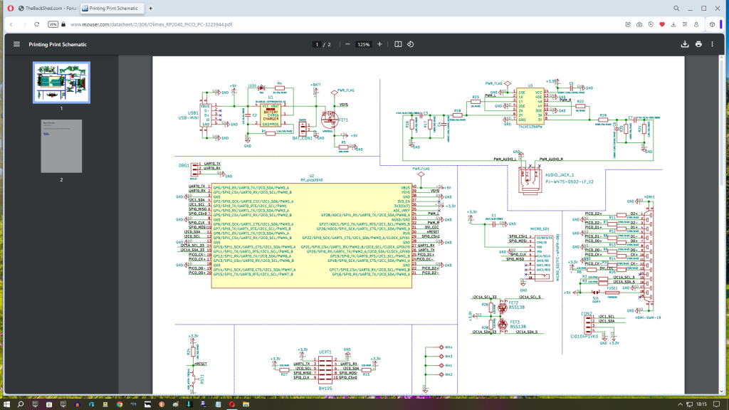
Mick, you seem more informed about olimex board than me. I don't know why gp26 and gp28 need joining. If I made a hdmi usb 2350 board then no problems? sound and adc work like usb vga 2350?.. which not tested adc. how to wire hdmi to 2350, need a header and resistors?  |
||||
| Mixtel90 Guru Joined: 05/10/2019 Location: United KingdomPosts: 6761 |
MMBasic's audio wants both channels to be on the same PWM, where they use A and B outputs. GP26 and GP27 would be fine for this as they ae on PWM5. The Olimex board has used GP28 (PWM6A) and GP27 (PWM5B) for audio and put GP28 on the DVI_CEC signal. This seems a weird choice. Why take the A channel from one PWM and the B channel from another? In fact, the whole of the audio side is odd. They took the PWM output, put it through a logic buffer then fed it into the simplest RC filter that was first used on the Micromite (except that they took the DC off the output). They put some resistors in to run an extra buffer too but then disabled it. Very strange and they don't seem to have gained anything. By linking GP26 to GP28 you are getting the right channel from GP27, the left channel will appear on GP26 which is then linked to GP28 so that it can appear as audio. The audio connections for the RP2350 and the RP2040 are identical when running MMBasic. . Edited 2024-11-18 05:59 by Mixtel90 Mick Zilog Inside! nascom.info for Nascom & Gemini Preliminary MMBasic docs & my PCB designs |
||||
| stanleyella Guru Joined: 25/06/2022 Location: United KingdomPosts: 2109 |
What does OPTION HDMI PINS 1, 3, 7, 5 mean? Is there a hdmi socket to 2350 circuit please? https://www.aliexpress.com/item/1005004837318611.html |
||||
| Page 1 of 2 |
|||||