
|

|
Forum Index : Microcontroller and PC projects : Add a remote control to a Harman Kardon HK6350R amplifier.
| Page 1 of 2 |
|||||
| Author | Message | ||||
| Marcel27 Regular Member Joined: 13/08/2024 Location: NetherlandsPosts: 53 |
This is a continuation of my comment in pil99's thread about IR Remote Control Rx and Tx for Philips RC-5 Protocol. I do not want to hijack his thread so I start my own. I have a beautiful vintage amplifier, HK6350R, without a remote. The device had some strange problems, the volume runs high or low at random or dropped random in standby mode. The problem was the M50761 processor IC201. After I removed this chip everything worked normal albeit without remote control. I built the example in the MMBasic manual with an infrared receiver and the simple program example. I had to add 2 resistors of 3k3 and 2k2 because the receiver is fed with 5V. But the first test went smoothly. edit SetPin GP6, IR Dim INTEGER DevCode, KeyCode IR DevCode, KeyCode, IRInt Do 'body Loop Sub IRInt Print "Received device = " DevCode ", key = " KeyCode End Sub ESC:Exit F1:Save F2:Run F3:Find F4:Mark F5:Paste Below you can see the results of the test, volume +, volume -, Power On and Power Off. 'Test with TFMS 5360 IR receiver 5V type and Harman Kardon substitue remote HK AVR145 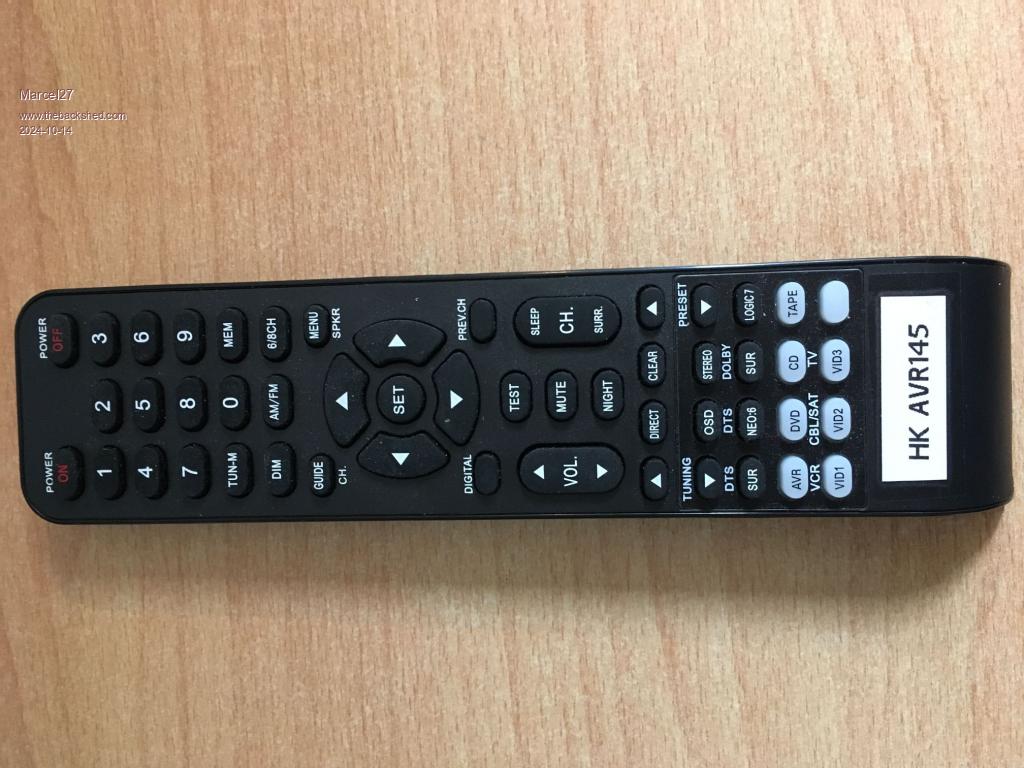 Received device = 270, key = 227 'volume up Received device = 270, key = 19 'volume down Received device = 270, key = 3 'power on Received device = 270, key = 249 'power off The next step is to set up an IR transmitter with a 2nd PICO and check if the communication can be emulated from the HK-remote. If that works, the next step is to modify the program so that it can be embedded in the HK6350R electronics. To be continued Edited 2024-10-14 00:39 by Marcel27 If you use AI, you lose your mind. |
||||
| Plasmamac Guru Joined: 31/01/2019 Location: GermanyPosts: 554 |
Like the idea Plasma |
||||
| Marcel27 Regular Member Joined: 13/08/2024 Location: NetherlandsPosts: 53 |
I made a mistake in my above story. It has already been demonstrated that the Pico can pick up a signal with the infrared sensor. Now I can start to figure out how the Pico can be integrated into the amplifier. Investigating if the Pico works as a transmitter is not necessary for this purpose.  The next thing that needs to be done is to look at the operation of the TC4028 and the LB1641. The first is a BCD to decimal decoder and the second is a bi-directional motor control. The motor control has its input on pins 5 (IN1) and 6 (IN2) and has a switching point of 1.5V. Everything above 2 V is High. Both pins H or L is the brake. In fact, they can be controlled directly bythe Pico if the BCD-dec decoder is bypassed in the new circuit. However the situation around the TC4028 must first be investigated. There are still a few loose transistors included in the circuit. IMOH, it's all designed in a very cumbersome way, I think the BCD-dec decoder could have been omitted and the motor control could have been controlled directly from the processor. They're going to make things difficult by toggling between (ABCD inputs) -> (Dec output) HHHL and LLLH to make Q7 or Q8 high. They could have used just 2 pins on the processor voor Q7, Q8 (up/down). Of course it's also possible that I'm missing something, that happens more often. This is my quick conclusion. Edited 2024-10-14 19:18 by Marcel27 If you use AI, you lose your mind. |
||||
| phil99 Guru Joined: 11/02/2018 Location: AustraliaPosts: 2135 |
Some thoughts on using a Pico for this. As noted above, it would be easiest to replace both IC201, IC202 and associated transistors with the PicoMite. The inbuilt IR command does not decode the "Repeat" pulses that the remote outputs to indicate a continuous button press, so to continuously raise / lower the volume needs a work-around. <Edit> Tested a couple of remotes. After a few hundred mS of repeat pulses they repeat the whole code so you may not need to worry about this. The code below has been edited to take advantage of this by reducing the timeout to 500mS. The output variables of IR DevCode, KeyCode, IRInt hold their values until another button is pressed. You can use that to advantage by stopping the motor when any other button is pressed. The volume could steadily raise / lower until that is pressed or the time-out is reached. A starting point for the code could be something like:- Const Up% = (270 << 8) + 227 '270=DevCode and 227=KeyCode for Up Button Const Down% = (270 << 8) + 19 '270=DevCode and 19=KeyCode for Down Button Const Pon% = (270 << 8) + 3 '270=DevCode and 3=KeyCode for On Button Const Poff% = (270 << 8) + 249 '270=DevCode and 249=KeyCode for Off Button SETPIN GP0, IR SETPIN GP1, Dout 'Vol up SETPIN GP2, Dout 'Vol down SetPin GP3, Dout 'Power IR DevCode, KeyCode, IRInt Sub IRInt T = Timer DevKey = (DevCode <<8) + KeyCode if DevKey = Up% then pin(gp1) = 1 pin(gp2) = 0 endif if DevKey = Down% then pin(gp1) = 0 pin(gp2) = 1 endif if DevKey = if (DevKey <> Up%) and (DevKey <> Down%) then 'quick stop pin(gp1) = 1 'Both high for braking pin(gp2) = 1 pause 200 'braking period pin(gp1) = 0 pin(gp2) = 0 endif 'Select Case would be better but that is the idea. If DevKey = Pon% Then Pin(gp3) = 1 If DevKey = Poff% Then Pin(gp3) = 0 End Sub Do If (Timer - T) > 500 then 'set a time limit for the motor run time pin(gp1) = 0 pin(gp2) = 0 endif loop End Another option would be to modify my NEC IR Receiver program to also decode the Repeat pulses. Edit. The code above is tested and working (with different IR codes and driving LEDs rather than a pot). Edited 2024-10-15 16:56 by phil99 Footnote added 2024-10-15 21:15 by phil99 Just noticed a careless copy/paste in the code above. This line:- if DevKey = if (DevKey <> Up%) and (DevKey <> Down%) then 'quick stop shoold be:- if (DevKey <> Up%) and (DevKey <> Down%) then 'quick stop |
||||
| Marcel27 Regular Member Joined: 13/08/2024 Location: NetherlandsPosts: 53 |
Thanks for your thoughts, I appreciate it. I had a written explanation of the whole circuit that took me more than an hour but I lost it due to switching browser planes   . .The upshot of the story is that I agree with you to remove the ICs and transistors in the circuit or at least cut the printed circuit traces to disabled the BDC-dec function and get bare access to the LB1641 motordriver IC. I looked at some other information of a Sony TAF319R unit. There they use the same processor M50761-291P, but it has a complete different function, different firmware. The device IC201 might be a SIRCS decoder with NEC protocol firmware? If you use AI, you lose your mind. |
||||
| Marcel27 Regular Member Joined: 13/08/2024 Location: NetherlandsPosts: 53 |
The Sony infrared sensor is a SBX1619-52 with TTL level output. The transistors on the right side are Q209, Q210. The transistors Q206, Q208 and IC202 will be removed. The two transistors Q209 and Q210 will be reused as level translators for the control of the LB1641. I have to test how these transistors behave when they are driven by the Pico with 3.3V. When the amplifier is switched on in the normal usage situation, pins 4 and 11 of IC202 are low. In the new situation, these are connected to 5V and R213 and R214 serve as pull-up resistors. LB1641 is on brake when both inputs are low or high. When IC201 pin 1 is connected to ground, the system goes into standby. In normal operation, there is 3.4V on this pin. I have to check whether this can be solved with a voltage divider or whether a transistor must be used, for example Q208 when the amplifier is switched. To be continued. If you use AI, you lose your mind. |
||||
| Mixtel90 Guru Joined: 05/10/2019 Location: United KingdomPosts: 6772 |
Oh, that's shouting out for a replacement PCB with a Pico on it. :) Mick Zilog Inside! nascom.info for Nascom & Gemini Preliminary MMBasic docs & my PCB designs |
||||
| Marcel27 Regular Member Joined: 13/08/2024 Location: NetherlandsPosts: 53 |
Mixtel90, it probably won't be done as professionally as you suggest.  A lot of hot glue etc. A lot of hot glue etc.  If you use AI, you lose your mind. |
||||
| Mixtel90 Guru Joined: 05/10/2019 Location: United KingdomPosts: 6772 |
Well, if you want a PCB designing throw me the circuit that you want and a drawing of the board with size, fixing positions and positions of the connectors etc. and I'll draw one up for you. It's not as if there's a lot of ancillary components from the looks of things. Possibly some level shifting. Just bear in mind that the price from JLCPCB won't be the special offer price if the board is longer than 100mm. It's a rather lovely old amp. :) Mick Zilog Inside! nascom.info for Nascom & Gemini Preliminary MMBasic docs & my PCB designs |
||||
| Marcel27 Regular Member Joined: 13/08/2024 Location: NetherlandsPosts: 53 |
Mick, Thank you for the offer to design a printed circuit board. From the many postings, I gather that you are an accomplished pcb designer. The pcbs you have made look beautiful. I could not match you. I am a practical person myself and usually use a Vero hole printed circuit board with some free wiring. In the meantime I have read up on the use of pcb software here because I also like it as a pastime, I am retired after all. Without thinking I would have taken KiCad but given the comments on the way of working within KiCad I am orienting myself towards other software. Also because in this case I do not want to work from a circuit design. I think Sprint Layout is a good alternative. 45 years ago I made an Eurokaart printed circuit board design for an IEEE mini-bus system with Meccanorma symbols and adhesive tape of 1, 2 and 3 mm and after that I did not design any more printed circuit boards until almost 3 years ago. Then I made an amplifier pcb in EasyEDA and I liked that. I saw afterwards that the price was very high for 2 pcb's and then I refrained from submitting the pcb order, €120 for 2 pcb I found much too expensive. I have to say that the prices at the moment are very "reasonable" for the numbers and dimensions. Of course it was a far from standard size. Nevertheless I find a "professional" solution for this Harman Kardon amplifier better, also because these types of amplifiers do well on the second hand market and if the adjustments are done properly you can set a good price. For now I first make a free wired design to test if I have thought of everything. In fact you only need 5 wires from the Pico to the amplifier, PON, Volume up, Volume down, GND and VSYS (5V). If I need your knowledge and skills I will certainly bother you. Edit: corrected some typos and added amp photo. It is a nice amp and it had some problems when I bought it. It was repaired by another repair guy but it had still the random remote issues and some problem with the bias current of one channel. The guy had "repaired" some bad soldering joints but introduced by that a shortage. Fortunately not a severe shortage but you could hear the distortion in one channel and the bias current was fixed at 0 mA. It took me 1 hour to disassemble the mainboard because of the many soldering connections and more time to find the tiny shortage. This amp is far from service friendly built but the sound is goooooood! Edited 2024-10-17 18:35 by Marcel27 If you use AI, you lose your mind. |
||||
| Marcel27 Regular Member Joined: 13/08/2024 Location: NetherlandsPosts: 53 |
@Phil99 Yes, I already found that typo and corrected that in my version and did not take the effort to report it. Your software example does its job and it is a good start. Thanks again. If you use AI, you lose your mind. |
||||
| Mixtel90 Guru Joined: 05/10/2019 Location: United KingdomPosts: 6772 |
My old NAD 3020 is from the same era. Another nice design and a bit of a pig to work on! Lovely sound though - a bit valve-like at times. Mick Zilog Inside! nascom.info for Nascom & Gemini Preliminary MMBasic docs & my PCB designs |
||||
| Marcel27 Regular Member Joined: 13/08/2024 Location: NetherlandsPosts: 53 |
Thought about your remark. I removed all unnecessary components from the PCB. Everything still works as it should and drew a schematic of the remaining components. Still have to test it in real live. If you use AI, you lose your mind. |
||||
| stanleyella Guru Joined: 25/06/2022 Location: United KingdomPosts: 2115 |
The big electrolytic caps look bulging? |
||||
| Mixtel90 Guru Joined: 05/10/2019 Location: United KingdomPosts: 6772 |
You'll probably know if they are getting bad by the increased hum level with the volume set to minimum. I wouldn't let it concern me too much. Electrolytics are generally designed to split neatly along the top to vent pressure if they fail completely, blowing out that insulating cover which helps keep the mess in the general area. At one time they weren't and could go with quite a bang! I don't change any capacitors unless they are definitely faulty. The only exception are the anode-grid coupling caps on valve amps where even the tiniest leakage will mess up the bias of the following stage. Modern caps are much, much better than old ones in that respect and changing them might save you the cost of a new output transformer. Mick Zilog Inside! nascom.info for Nascom & Gemini Preliminary MMBasic docs & my PCB designs |
||||
| Marcel27 Regular Member Joined: 13/08/2024 Location: NetherlandsPosts: 53 |
Yep they look like, but if you feel the top with your finger and push on it the top beneath is flat. It is just the plastic top plate. Edited 2024-10-30 02:44 by Marcel27 If you use AI, you lose your mind. |
||||
| stanleyella Guru Joined: 25/06/2022 Location: United KingdomPosts: 2115 |
old gear and caps dry. looks linear supply. caps in switch mode supplies bulging is worst but long time since I opened a case and it's full of feathers, when a cap blows. I got some old amps like a Sansui feed forward feedback?, still sounds good but music is compressed now to make it sound louder so hi fi is retro. as someone said to me, "I don't care as long as it's got bass" |
||||
| Marcel27 Regular Member Joined: 13/08/2024 Location: NetherlandsPosts: 53 |
Checked the DC voltage on my scope, nice smooth signal. 45 years ago I found a bad cap in an Delta Power Supply. I know how a "DC" voltage looks like when a cap is dry or rotten after a Graetz rectifier.  If you use AI, you lose your mind. |
||||
| Marcel27 Regular Member Joined: 13/08/2024 Location: NetherlandsPosts: 53 |
I built the circuit as indicated in the KiCad schema but it did not work. I read somewhere on the net that these Sony sensors sometimes gave problems due to the presence of dried out capacitors, so I dismantled the sensor. There appeared to be no capacitors in it. I wanted to know the details and made a simple circuit to measured the sensor with an oscilloscope. It appeared that the sensor did work, but that there was a square wave on the output. After I had modified the circuit with a DTC144E (level shifter) transistor and had offered the signal to the Pico, the signal was converted. The Sony sensor does work but to a certain extent. PON and POF buttons were not read by the Sony. Values did come through but not all buttons were read correctly. With another sensor, for example the HRM36002P, which looks like a TSOP1738, all buttons were read. I am not stuck with the original Sony sensor and therefore choose the sensor that gives the best result. The square wave at the output of the Sony SBX1619-52. 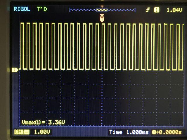 Signal from the Sony sensor. 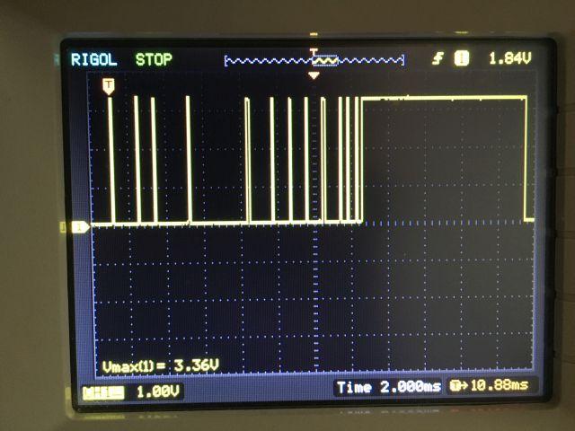 Signal from the HRM36002P sensor. 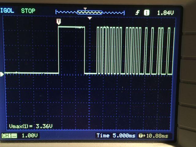 The Sony sensor. 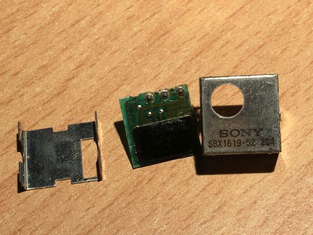 Next step is changing the KiCad drawing. If you use AI, you lose your mind. |
||||
| Mixtel90 Guru Joined: 05/10/2019 Location: United KingdomPosts: 6772 |
It's probably 38kHz modulated IR. Some receivers decode this and output a simple TTL signal. Others are basically a IR diode with an amplifier and leave the decoding to external circuitry. Mick Zilog Inside! nascom.info for Nascom & Gemini Preliminary MMBasic docs & my PCB designs |
||||
| Page 1 of 2 |
|||||