|

|
Forum Index : Microcontroller and PC projects : PicoMite: PCF8575 I2C I/O Expander
| Page 1 of 2 |
|||||
| Author | Message | ||||
| thwill Guru Joined: 16/09/2019 Location: United KingdomPosts: 4036 |
Hi folks, Would one of these be as trivial as I suspect to drive from MMBasic on the PicoMite ?  Yes, I know I'm not supposed to be getting distracted  . .Best wishes, Tom Game*Mite, CMM2 Welcome Tape, Creaky old text adventures |
||||
| Volhout Guru Joined: 05/03/2018 Location: NetherlandsPosts: 4223 |
The original PCF8574 is a 5V I2C device. The PCF8575 looks like a dual 8574. But is works on 3.3v also. I think this would work fine on a pico or cmm2. 16 extra digital IO’s Software interface is simple, to send data out, you write chip address and the 16 bits(2 bytes). To read inputs,you have to make sure you write the bits you use as input, with output value 1 Then you read 2 bytes. No registers to worry about. Hardware you needed know that the outputs are switching to ground. A LED must be connected between the output and 3v3 Volhout Edited 2024-09-06 03:58 by Volhout PicomiteVGA PETSCII ROBOTS |
||||
| stanleyella Guru Joined: 25/06/2022 Location: United KingdomPosts: 2120 |
I only tried https://www.microchip.com/en-us/product/mcp23017 but it's fine/// is it? |
||||
| PhenixRising Guru Joined: 07/11/2023 Location: United KingdomPosts: 857 |
Don't know if this is of any help |
||||
| thwill Guru Joined: 16/09/2019 Location: United KingdomPosts: 4036 |
Actually I'm looking to read (a lot of) buttons rather than drive LEDs ... sometimes I think there are only two things in hobbyist electronics  . .Perhaps the PCF8575 may not be the best thing, looks like I need a pull-up resistor on every input so that's going to be drawing x16 current with none of the buttons down ? Tom Edited 2024-09-06 05:35 by thwill Game*Mite, CMM2 Welcome Tape, Creaky old text adventures |
||||
| lizby Guru Joined: 17/05/2016 Location: United StatesPosts: 3150 |
I've played with these or similar, but can't locate code. scratch this ]Isn't the point of writing 1s to it (per Volhout), that if you read back a zero instead of a 1, it means your button connecting to 0V has been pressed?] Isn't the point of writing 1s to it (per Volhout), which, because things are inverted, represents a 0, that if you read back a zero instead of a 1, it means your button connecting to 3V3 has been pressed? Here's code to write to the similar PCF8574 (8-bit): ' i2c_pcf8574.bas Dim integer k1=&b10101010,k2=&b01010101 SetPin 6,7,i2c I2C open 100,100 Do I2C write &h20,0,1,k1: I2C write &h12,0,1,k2: Pause 500 I2C write &h20,0,1,k2: I2C write &h21,0,1,k1: Pause 500 If Inkey$="x" Then Exit Loop I2C write &h20,0,1,255: I2C write &h21,0,1,255 ' turn off (This inverted logic confuses me regularly.) ~ Edited 2024-09-06 06:19 by lizby PicoMite, Armmite F4, SensorKits, MMBasic Hardware, Games, etc. on fruitoftheshed |
||||
| stanleyella Guru Joined: 25/06/2022 Location: United KingdomPosts: 2120 |
I only wanted buttons not high speed. I got code from a nice forum guy mode 1 option autorun on OPTION EXPLICIT OPTION DEFAULT NONE dim integer porta_bits,portb_bits 'SETPIN gp20, gp21, I2C 'I2C OPEN 100,100 const mcp23017 = &h20 ' A2, A1, A0, R/W all connected to 0V Const i2caddr=mcp23017 const IODIRA = &h00 ' Port A IO Direction register DEFAULT = I/P const IODIRB = &h01 ' Port B IO Direction register DEFAULT = I/P const IOCON = &h0A ' IO Expander config register - address &h0B accesses same register const GPIOA = &h12 ' Port A General purpose register const GPIOB = &h13 ' Port B General Purpose register const OLATA = &h14 ' Port A latch register const OLATB = &h15 ' Port B latch register const GPUPA = &h0C ' Port C pull-up register const GPUPB = &h0D ' Port B pull-up register ' I2C WRITE MCP23017,0,2,IODIRA,255 ' set direction to input I2C WRITE MCP23017,0,2,IODIRB,255 ' set direction to input I2C WRITE MCP23017,0,2,GPUPB,&hff ' set weak pullups on all ' Font 5 CLS ' Do 'then when you read: 'I2C WRITE MCP23017,0,1,GPIOB ' set the register to read 'I2C READ MCP23017,0,1,portb_bits ' read the B port get_portb_bits text 0,20,bin$(portb_bits,8) text 0,60,str$(portb_bits) Pause 100 Loop sub get_portb_bits I2C WRITE MCP23017,0,1,GPIOB ' set the register to read I2C READ MCP23017,0,1,portb_bits ' read the B port end sub   Edited 2024-09-06 06:27 by stanleyella |
||||
| lizby Guru Joined: 17/05/2016 Location: United StatesPosts: 3150 |
Here is part of my earlier struggle, with Volhout's explanation below which made me (at the time) better understand how it worked. No resistors involved. PicoMite, Armmite F4, SensorKits, MMBasic Hardware, Games, etc. on fruitoftheshed |
||||
| thwill Guru Joined: 16/09/2019 Location: United KingdomPosts: 4036 |
I don't know ;-) it sometimes seems that a lot of what is written in hobbyist articles is by people as clueless as I, which is what makes TBS so helpful. I think what you are suggesting is pin -> button -> 3v3 ... If you press the button the pin goes high, but in the absence of a resistor how much current is the pin now being asked to sink ? I suspect this is a teaching moment. Best wishes, Tom Game*Mite, CMM2 Welcome Tape, Creaky old text adventures |
||||
| stanleyella Guru Joined: 25/06/2022 Location: United KingdomPosts: 2120 |
I like lizbys preference. I used the weak pull ups and checked pins grounded works great as stepper motor driver.. arduino https://www.youtube.com/watch?v=s5-5DNa36jk Edited 2024-09-06 07:00 by stanleyella |
||||
| barewires Newbie Joined: 13/04/2015 Location: United KingdomPosts: 30 |
Today I received a Bus Pirate 5. I have used the V3 in the past and mostly for I2C monitoring and probing. https://buspirate.com/bus-pirate-5-rev-10-now-available/ |
||||
| Mixtel90 Guru Joined: 05/10/2019 Location: United KingdomPosts: 6779 |
I always prefer input low to activate. It's almost an industry standard and goes along with things like active low chip select lines. Inputs do draw some current when not operated though. However, inputs also source some current into the pull-down resistor on active high inputs. You need to look at the spec of the input to see which is the better case if you are working with a lot of inputs on a battery supply. If you have a serious amount of buttons to read then a matrix is the way to go - like they use for keyboards. :) MMBasic can read 16 buttons with 8 bits. Mick Zilog Inside! nascom.info for Nascom & Gemini Preliminary MMBasic docs & my PCB designs |
||||
| stanleyella Guru Joined: 25/06/2022 Location: United KingdomPosts: 2120 |
or just use a keyboard. |
||||
| lizby Guru Joined: 17/05/2016 Location: United StatesPosts: 3150 |
I now think I got that right the first time but wrong the second. You write 1s; if you read back with no button pressed, you get 1s; if you press the button connected to 0V, you get 0, which means the button is pressed. PicoMite, Armmite F4, SensorKits, MMBasic Hardware, Games, etc. on fruitoftheshed |
||||
| Mixtel90 Guru Joined: 05/10/2019 Location: United KingdomPosts: 6779 |
Active low inputs have the advantage now that they are compatible with the RP2350. :) Mick Zilog Inside! nascom.info for Nascom & Gemini Preliminary MMBasic docs & my PCB designs |
||||
| thwill Guru Joined: 16/09/2019 Location: United KingdomPosts: 4036 |
I want to read 13 buttons using 2-3 pins ... ... I could of course do this by connecting 2 x 8-bit PISO shift-registers (CD4021) and a couple of resistor arrays (pull-up) but I thought that (a) I should try and learn some new tricks, and (b) I2C might be faster than clocking the data out of the shift-registers. EDIT: I'd also like to do it "cheaply" which is why I wasn't looking at the Microchip devices. Best wishes, Tom Edited 2024-09-06 08:18 by thwill Game*Mite, CMM2 Welcome Tape, Creaky old text adventures |
||||
| lizby Guru Joined: 17/05/2016 Location: United StatesPosts: 3150 |
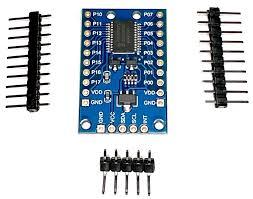
Well, I had a PCF8575, so I wired it up. It did not work as I expected. For me it worked without writing any output, with switching to high. Here's the program (it was convenient for me to power it from pin 34, so the program sets that high). Dim integer inp(2) SetPin 6,7,i2c SetPin 34,dout: Pin(34)=1 ' power the PCF8575 I2C open 100, 1000 Do I2C read &h20,0,2,inp() Print Hex$(inp(0));"/"Hex$(inp(1));" "; Pause 3000 Loop I connected a wire to 3V3 and moved it variously to different pins on the two ports. Every 3 seconds the program prints the hex value of the 16 PCF8575 pins. Here is sample output: 0/0 0/0 0/0 0/40 0/20 0/20 0/0 0/80 0/1 0/2 0/4 0/4 0/8 0/8 0/10 0/10 0/20 10/0 2/0 1/0 80/0 80/0 80/0 So for this simple test, the default pin value is low, and connecting it to VDD (as with a button) brings it high. Not the same as the PCF8574. The module I have looks like the one you pictured, including the oddly labelled pins of the upper port, shown as p10 through p17. ~ Edited 2024-09-06 11:27 by lizby PicoMite, Armmite F4, SensorKits, MMBasic Hardware, Games, etc. on fruitoftheshed |
||||
| Turbo46 Guru Joined: 24/12/2017 Location: AustraliaPosts: 1611 |
KISS, If you don't want outputs or interrupts why make it more complicated than necessary? Bill Keep safe. Live long and prosper. |
||||
| Mixtel90 Guru Joined: 05/10/2019 Location: United KingdomPosts: 6779 |
RP2040-Zero over I2C? Program it to do what you like - it could even trigger an interrupt on pin change. Mick Zilog Inside! nascom.info for Nascom & Gemini Preliminary MMBasic docs & my PCB designs |
||||
| thwill Guru Joined: 16/09/2019 Location: United KingdomPosts: 4036 |
That sounds like overkill, likewise using an 80-pin 2350 so there is more GPIO. Tom Game*Mite, CMM2 Welcome Tape, Creaky old text adventures |
||||
| Page 1 of 2 |
|||||