
|
|
Forum Index : Microcontroller and PC projects : Pico LC meter
| Page 1 of 3 |
|||||
| Author | Message | ||||
| Volhout Guru Joined: 05/03/2018 Location: NetherlandsPosts: 5945 |
What is everybody working on... Well, this is my latest addition to the PicoMite family. The PicoMite LC meter This is not my own design, but a PicoMite implementation of a design that is published on the internet years and years ago. I breadboarded the design, and used the breadboard since. But I liked it so much, I got a more solid housing now. The LC meter can measure capacitance between 1pF and 100nF, and inductors between 0.1uH and over 15mH. It is based on a a tuned oscillator, and addad capacitance and inductance off-tunes the oscillator. The frequency changes of the oscillator is measured, and from there, with simple electronics math, the values are calculated and displayed. This is the (arduino) circuit diagram that is used as a basis: 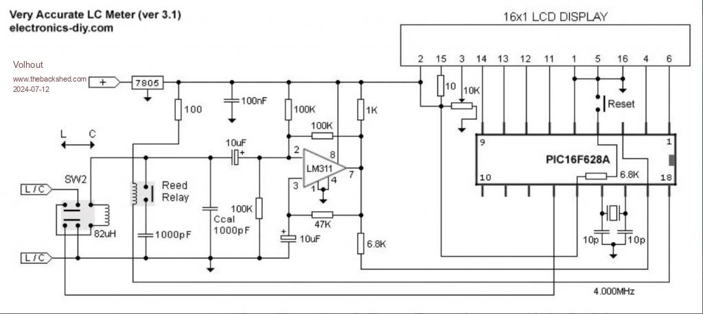 And the breadboard version 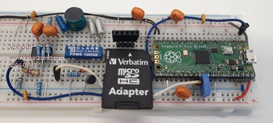 To adapt the circuit to the Pico 3.3V levels the output (the 6.8k resistor) receives a 10k pulldown, and the relay output gets a NPN driver transistor with 10k base resistor. The re-vamped circuit looks like this now 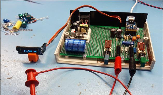 It is in a G738 box (same as the CMM2), and has a 4 euro phone charger as power supply. Since the charger outputs quite a lot of ripple, and old 4700uF cap came to the rescue. Not visible is the copper foil under the PCB, to shield the bottom from the outside world. The Pico Zero uses the PIO to measure the oscillator frequencies up to 7 digits. It uses PIO 1 state machines 2 and 3, simply because the code is "borrowed" from my frequency counter that uses the other state machines from pulse and period measurements. The "green" button switches between capacitance and inductance mode. The "blue" button acts as a push button, and zero's the reading to compensate for wires, or adaptor (note you can measure down to 0.01pF). When there is interest I may draw up a complete schematic, but the circuit looks simple enough to do without. If you are building, the 1000pF capacitor in the circuit diagram that is NOT identified as Ccal, needs to be a stable and accurate one. Try to find a 1% part. The one identified as Ccal needs to be stable as well, but not accurate. Any film capacitor, or NP0 capacitor will do. The code 'capacitor and inductor meter on RP2040 'capacitors and inductors are added to a resonant circuit, and the frequency 'shift is used to calculate the component under test 'a reference capacitor (Cref=1030pF) is used to calibrate the system dynamically 'RP2040 PIO is used to measure the resonant frequency accurately. '--------------------------- version control ----------------------------------- ' ' V01 measures system components Cbase and Lbase ' V03 First working version, includes ZERO and IND/CAP ' V04 Adds LCD display SSD1306I2C32 (128x32 pixels) ' V05 Ranging optimized '------------------------- MMBASIC MAIN CODE --------------------------------- ' setup 'analog CAL component value Cref=1030e-12 '1030 pF = main calibration parameter Cbase=700e-12 'default value Lbase=63e-6 'default value VAR restore 'restore previous Lbase Cbase 'set the pin to switch in CAL relay SetPin gp4,dout Pin(gp4)=0 'init the pin to detect L or C measurement mode SetPin gp5,din,pullup 'capacitor (=1) or inductor (=0) SetPin gp6,din,pullup 'calibrate (=1) 'set up the frequency coounter on PIO setup_pio 'variables and constants used in the frequency counter Dim r%(3),c% 'define variables, r%() only used to empty fifo set_gate 0.2 'default gate time in seconds ' main loop 'measure frequency with GP4 low (base system) and GP4 high (base + Cref) 'use this to determine Cbase and Lbase of the resonant system Do 'measure f1% (base system) Pin(gp4)=0 Pause 10 frequency ff1%=c% 'measure f2% (base + Cref) Pin(gp4)=1 Pause 10 frequency ff2%=c% 'calculate cap and ind from these frequencies If ff1%<>ff2% And ff1%>0 And ff2%>0 Then 'prevent divide by zero if pin(gp6)<>oldkey then cls oldkey=pin(gp6) If oldkey=1 Then 'calculate Cbase Cbase = Cref*(ff2%^2) / (ff1%^2 - ff2%^2) 'calculate Lbase Lbase=1/(4*(Pi^2)*(ff1%^2)*Cbase) 'debug print 'Print "Cbase=";Str$(Cbase*1e12,4,2);" pF Lbase=";Str$(Lbase*1e6,3,3);" uH" Text 64,8,"Cb = "+Str$(Cbase*1e12,4,2)+" pF",CM Text 64,24,"Lb = "+Str$(Lbase*1e6,3,3)+" uH",CM VAR save Lbase,Cbase 'keep for next power up Else If Pin(gp5)=1 Then 'calculate C Cmeas = Cref*(ff2%^2) / (ff1%^2 - ff2%^2) - Cbase Cmeas=max(0,Cmeas) 'never negative select case Cmeas case <1e-9 Text 64,16,right$(" "+Str$(Cmeas*1e12,3,2)+" pF",10),CM,7,2 set_gate 0.2 case <1e-8 Text 64,16,right$(" "+Str$(Cmeas*1e9,2,3)+" nF",10),CM,7,2 set_gate 0.2 case <1e-7 Text 64,16,right$(" "+Str$(Cmeas*1e9,3,2)+" nF",10),CM,7,2 set_gate 0.4 case else Text 64,16,right$(" %"+Str$(Cmeas*1e9,4,1)+" nF",10),CM,7,2 set_gate 1 end select Else 'calculate L Lmeas=1/(4*(Pi^2)*(ff1%^2)*Cbase) - Lbase Lmeas=max(0,Lmeas) 'never negative select case Lmeas case <1e-5 Text 64,16,right$(" "+Str$(Lmeas*1e6,2,3)+" uH",10),CM,7,2 set_gate 0.2 case <1e-4 Text 64,16,right$(" "+Str$(Lmeas*1e6,3,2)+" uH",10),CM,7,2 set_gate 0.2 case <1e-3 Text 64,16,right$(" "+Str$(Lmeas*1e6,4,1)+" uH",10),CM,7,2 set_gate 0.2 case else Text 64,16,right$(" "+Str$(Lmeas*1e3,2,3)+" mH",10),CM,7,2 set_gate 0.4 end select End If End If End If Loop '------------------------------- SUBS --------------------------------------- sub set_gate a 'set the gate time, and associated counter for PIO gate_time = a 'gate time in seconds gate_clocks% = gate_time*f2 - 1 'for 1MHz PIO clock as integer (n counts (n-1...0)) end sub Sub setup_pio 'PIO machine 1.2 generates a progr. gate signal on GP2 (side set pin GP2) 'PIO machine 1.2 sets GP2 and GP3 output for both state machines 1.2 and 1.3 'PIO machine 1.3 uses the GP2 gate signal to count GP0 pulses, GP3 is NO SIGNAL 'PIO program ----------------------------------------------------------------- 'PIO 1.2 (gate) 'adress data mnemonics comment ' &h10 E083 set pindir 00011 'set GP2,GP3 to output for both state machines '.wrap target ' &h11 90A0 pull block .side(1) 'pull data from FIFO into OSR when available ' &h12 B027 mov(x,osr) .side(1) 'load gate time (in clock pulses) from osr ' &h13 0053 jmp(x_dec, this line) .side(0) '1 cycle count down + gate low '.wrap ' &h14 0000 not used 'PIO 1.3 (count) '.wrap target ' &h15 A02B mov(x,-1) .side(0) 'x = -1 (clear counter) ' &h16 2082 wait(1,gp2) .side(0) 'sync to GATE signal ' &h17 2002 wait(0,gp2) .side(0) 'detect falling edge of gate signal ' &h18 3000 wait(0,gp0) .side(1) 'wait for risig edge input signal ' &h19 3080 wait(1,gp0) .side(1) 'wait for falling edge input signal ' &h1A 00DC jmp(gp2, to 0x1c) .side(0) 'continue counting (gateepuls ended ?) ' &h1B 0058 jmp(x_dec, to 0x18) .side(0) 'yes, count next pulse input ' &h1C A0C9 mov(isr,-x) .side(0) 'copy counter to isr ' &h1D 8000 push noblock .side(0) 'get value to FIFO '.wrap ' &h1E 0000 not used ' &h1F 0000 not used 'this is above program in data statements Dim a%(7)=(0,0,0,0,&h0053B02790A0E083,&h20022082A02B0000,&h005800DC30803000,&h8000A0C9) 'SETUP code SetPin gp0,pio1 'frequency counter input SetPin gp2,pio1 'gate signal SetPin gp3,pio1 'no signal output used to display input signal missing 'program above code in the chip in PIO 1 PIO program 1,a%() 'PIO configuration ------------------------------------------------------------ 'PIO 1.2 f2=1e6 '1 MHz frequency gate resolution e2=Pio(execctrl gp0,&h11,&h13) 'wrap target &h11, wrap &h13 p2=Pio(pinctrl 1,2,,,gp2,gp2,) 'GP2 side set, GP2/GP3 SET (for pindirs) PIO init machine 1,2,f2,p2,e2,0,&h10 'start from 0x10 'PIO 1.3 f3=126e6 '63 MHz frequency e3=Pio(execctrl gp2,&h15,&h1d) 'gp2 is PIN for cond jmp. wrap target &h15, wrap &h1D p3=Pio(pinctrl 1,,,gp0,gp3,,) 'GP0 base for inputs, GP3 out for SIDE SET PIO init machine 1,3,f3,p3,e3,0,&h15 'start from 0x14 -test. skip IO init, start at &h15 'Start both PIO sequencers PIO start 1,2 'this will wait for data to arrive in FIFO, then generate 1 gate PIO start 1,3 'this will start counter, waiting on adress &h17 for GP2 gate to become low End Sub 'measure frequency at GP0, check GP3 for "no signal" Sub frequency 'first check if there is no input signal. PIO 1.3 will be stuck at instruction &h18 or &h19 and 'side set pin GP3 will be high. If Pin(gp3)=1 Then 'debug 'Print "no input signal" Pause 200 Else 'put gate time in PIO 1.2 OSR (gate_ime is specified in PIO cycles: gate_clocks%) PIO read 1,3,4,r%() 'empty fifo from rubbish (only needed at start) PIO write 1,2,1,gate_clocks% 'this starts the gate pulse generator, single pulse 'wait gate time + few ms for printing data Pause (1000*gate_time + 200) 'get FIFO value PIO read 1,3,1,c% 'read value from FIFO (there is only 1 value in it) c%=c%/gate_time 'convert or Hz 'debug 'Print "GP0 frequency = ";c%;" Hz" EndIf End Sub Edited 2024-07-12 21:51 by Volhout PicomiteVGA PETSCII ROBOTS |
||||
| v.lenzer Senior Member Joined: 04/05/2024 Location: GermanyPosts: 117 |
I'm very interested! I read through the source and identified the GPs. Which GPs are you using for I2C? I didn't find that in the source because I'm sure you've put it in the OPTIONS. If it's not too much work, a schematic would be nice. Best wishes! Joachim |
||||
| JohnS Guru Joined: 18/11/2011 Location: United KingdomPosts: 4336 |
Er... it doesn't use I2C does it? John |
||||
| Volhout Guru Joined: 05/03/2018 Location: NetherlandsPosts: 5945 |
Hi Joachim, John, The Pico ZERO uses: OPTION SYSTEM I2C GP26,GP27 OPTION LCDPANEL SSD1306I2C32,RL So YES, it is an I2C display.... It is this simple..... The circuit diagram. It does not show the power supply and huge 4700uF capacitor, since that is not needed to make it work. Powering from the laptop USB works just as fine. 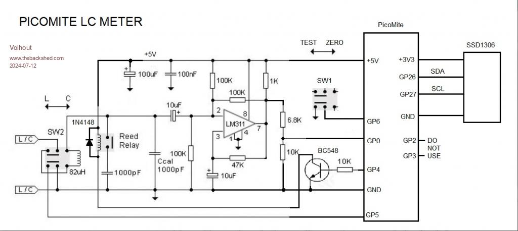 Volhout . Edited 2024-07-12 23:28 by Volhout PicomiteVGA PETSCII ROBOTS |
||||
| v.lenzer Senior Member Joined: 04/05/2024 Location: GermanyPosts: 117 |
Thank you very much!! Which circuit diagram software do you use? It looks like splan from ABACOM. If so, I would be happy to receive the file. Best wishes! Joachim |
||||
| Volhout Guru Joined: 05/03/2018 Location: NetherlandsPosts: 5945 |
Hi Joachim, This is MS Paint. Volhout PicomiteVGA PETSCII ROBOTS |
||||
| lizby Guru Joined: 17/05/2016 Location: United StatesPosts: 3788 |
What component library is used to make this circuit diagram with MS Paint? PicoMite, Armmite F4, SensorKits, MMBasic Hardware, Games, etc. on FOTS |
||||
| phil99 Guru Joined: 11/02/2018 Location: AustraliaPosts: 3294 |
It looks like Volhout used, for most of it, C&P from the original then added lines, boxes and text from the drawing palette. The transistor could be from a library or C&P from another circuit diagram. |
||||
| Mixtel90 Guru Joined: 05/10/2019 Location: United KingdomPosts: 8913 |
I can recommend TinyCAD for doing schematics on the PC. It's free. The component library isn't very big but it's not too bad to add your own parts. You do need to read the manual about that though. If you do it right it can export netlists but I don't. :) EasyEDA Pro is even better as you get a full PCB designer package for the same cost. :) Mick Zilog Inside! nascom.info for Nascom & Gemini Preliminary MMBasic docs & my PCB designs |
||||
| Volhout Guru Joined: 05/03/2018 Location: NetherlandsPosts: 5945 |
When I design a pcb for private use I use Kicad. But that is not often, most my projects are one of. So I use veroboard or similar. There are many here on the forum that design pcb's. Each has its own preference. In the past I used sprint 5. Volhout. PicomiteVGA PETSCII ROBOTS |
||||
| lizby Guru Joined: 17/05/2016 Location: United StatesPosts: 3788 |
Ah, cut/copy and paste. That makes sense. I use EasyEDA. Great program. I've even taken advantage of their option to have them make a new component. It took a number of emails and several iterations, but they got it right. PicoMite, Armmite F4, SensorKits, MMBasic Hardware, Games, etc. on FOTS |
||||
| v.lenzer Senior Member Joined: 04/05/2024 Location: GermanyPosts: 117 |
Hello Volhout! At the moment I can only find 1% capacitors with a value of 816 pF for the 1000 pF capacitors at a reasonable price. Shipping is usually more expensive than the item itself. Can I use it if I change Cref? If so, what value should Cref have? Best wishes! Joachim |
||||
| Volhout Guru Joined: 05/03/2018 Location: NetherlandsPosts: 5945 |
Hi Joachim, Yes, you can use 816pF as long as you put that valuing the program. But you can also do what I did. I used 470pF 1% parallel to 560pF 1%. Since these where the values I could purchase. It is all math, so if you just use thisvalue for Cref in the basic program, it is fine. Volhout Technical: Cref is switched parallel to the total capacitance. When trying to measure a 100nF capacitor, the 1000 pf makes 1% difference(101 versus 100). Since frequency depends on the square root of the capacitance, the frequency difference is only 0.01%. When your target is measuring larger capacitors, 2000pF may work even better than 1000pF. Edited 2024-07-14 03:59 by Volhout PicomiteVGA PETSCII ROBOTS |
||||
| Mixtel90 Guru Joined: 05/10/2019 Location: United KingdomPosts: 8913 |
You might find one labelled as 1nF or 0.001uF. Mick Zilog Inside! nascom.info for Nascom & Gemini Preliminary MMBasic docs & my PCB designs |
||||
| Volhout Guru Joined: 05/03/2018 Location: NetherlandsPosts: 5945 |
The LC meter has shown it's use. Today I repaired my old Grundig Yacht Boy 1100 transistor radio, I bought when I was 16 years old. It was amazing the plastics are still not brittle, so I could get it appart. I found the adjustment procedure (in French language, note this is a radio designed by Grundig France), and found one capacitor in the tuning circuit for FM to be bad (value less than 10% of the value). All in all it took a whole day to go through the test and adjustment procedure, but it was satisfying the radio performs again close to new. almost 50 years old. I am very satisfied seeing this radio working again, it was with me in so many adventures, trips, house renovations, paint jobs. I cleaned the thing, and it is ready for another 50 years. Volhout PicomiteVGA PETSCII ROBOTS |
||||
palcal Guru Joined: 12/10/2011 Location: AustraliaPosts: 2039 |
Our everyday listen is a 60 year old Ferris transistor radio, they actually had parts in them back then, not just a block of black plastic. "It is better to be ignorant and ask a stupid question than to be plain Stupid and not ask at all" |
||||
| Volhout Guru Joined: 05/03/2018 Location: NetherlandsPosts: 5945 |
Honestly, it will be for 3 years only. Starting 2027 all FM broadcast is converted to DAB. Then the radio is useless.. 1 month ago they converted the cable distribution, Both TV and radio. Sad.. . Edited 2024-07-14 07:39 by Volhout PicomiteVGA PETSCII ROBOTS |
||||
| Volhout Guru Joined: 05/03/2018 Location: NetherlandsPosts: 5945 |
Appart from the lettering on the front panel, it is complete,,, Inside the unit 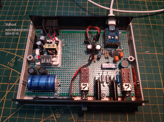 When you zero the unit, it shows what the corrections are (inductor and capacitor inside). 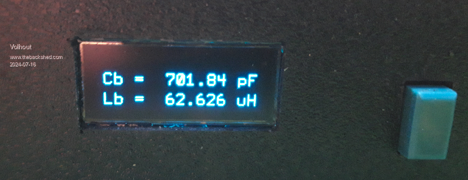 The unit in operation, measuring a 47pF ceramic capacitor, using a long coax cable with alligator clips, that is zero'ed out. Running from the 230V charger power suppy inside the box. 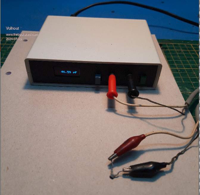 The display is small, but reading is clear enough to be readable. But I think the frequency counter (next project) needs a bigger display (more digits, so the font would become very small). The current display is "hot-glued" in it's frame. I did not bother to make a special glass for it (with my tools that always is uglier than the display itself). Volhout Edited 2024-07-16 05:49 by Volhout PicomiteVGA PETSCII ROBOTS |
||||
| v.lenzer Senior Member Joined: 04/05/2024 Location: GermanyPosts: 117 |
Hello Volhout! I have recreated your LC meter. Unfortunately, it doesn't want to work properly. Before I start measuring all the cables and components, I would first like to ask you if you can give me a hint. I changed Cref to 816e-12 in the program because I am using an 816 pF capacitor. I have also activated the debug messages in your program. So that I know whether the program has started, I display a message on the OLED for 2 seconds. The OLED is controlled correctly. For the test, I connected a capacitor with 816 pF to the terminals. After starting, the relay switches on and off regularly in time. However, no measured values appear on the display. The message on the console appears: "GP0 frequency = 555746560 Hz" and then the constant message: "no input signal". It doesn't matter if I switch SW2 to L or C and if I set SW1 to calibrate or not calibrate. It doesn't change anything if I don't have a capacitor on the terminals. Any ideas? Edited 2024-07-22 07:04 by v.lenzer Best wishes! Joachim |
||||
| Volhout Guru Joined: 05/03/2018 Location: NetherlandsPosts: 5945 |
Hi Joachim, The circuit consists of 2 blocks: 1 the oscillator using the LM311. 2 the frequency counter using the pico. First see if the oscillator works. Switch to capacitor test. If you disconnect the 6.8k resistor, there should be a nice square wave at the LM311 output (pin 7). It should be 5Vpp, some 500kHz…1MHz depending the capacitors and inductors used. If you do not have a scope to monitor this, but you have a voltmeter, then re-connect the 6.8 k resistor, and measure at pico pin1, gp0. There should be 1.4v to 1.8v dc at that pin ( 3.3v with 50% duty cycle. Volhout Edited 2024-07-22 15:27 by Volhout PicomiteVGA PETSCII ROBOTS |
||||
| Page 1 of 3 |
|||||
| The Back Shed's forum code is written, and hosted, in Australia. | © JAQ Software 2026 |
