|

|
Forum Index : Microcontroller and PC projects : PicoMite VGA Basic - new design
| Page 1 of 2 |
|||||
| Author | Message | ||||
| Mixtel90 Guru Joined: 05/10/2019 Location: United KingdomPosts: 6792 |
The result of last night's messing about. :) This is a PicoMite VGA, based on the PicoMite VGA Mini, that's been stripped down to almost the bare minimum. It's 90mm x 50mm and uses what I think are the easiest components to get. The only luxury is a 6-pin expansion port. 5 of the pins line up with those of the tiny RTC module so one of those can be easily fitted if required. It hangs out over the front edge of the PCB. It should be very easy to build as there's no PCB cutting to do and SMD components are kept to a minimum. I could have used a through-hole audio jack, I suppose, but this one is very easy to fit. Circuit & gerbers to follow. Mick Zilog Inside! nascom.info for Nascom & Gemini Preliminary MMBasic docs & my PCB designs |
||||
| Volhout Guru Joined: 05/03/2018 Location: NetherlandsPosts: 4237 |
Nice Mick, This is what I had in mind. Just looking at how the pins connect to the pico, the routing could be easier if you change the order of the connectors to K3(VGA)-K4-K2-K1. But this should be fine as well. I wonder if the LM1117 package is corrcct to size. Volhout PicomiteVGA PETSCII ROBOTS |
||||
| Mixtel90 Guru Joined: 05/10/2019 Location: United KingdomPosts: 6792 |
It can now accept two different sizes of VGA connector and am alternative uSD push-push socket as an alternative. I did consider that order for the connectors originally, but the positions of R2 & R3 seemed sensible so I based it on that. It's kept all signal wires pretty short. The LM1117T looks too thin to me, but as it's stood on its legs it'll be fine. :) I put the TO92 package on originally but they seem to be harder to get. I'm open to changing it though. Mick Zilog Inside! nascom.info for Nascom & Gemini Preliminary MMBasic docs & my PCB designs |
||||
| thwill Guru Joined: 16/09/2019 Location: United KingdomPosts: 4040 |
 ;-) Tom. Game*Mite, CMM2 Welcome Tape, Creaky old text adventures |
||||
| Mixtel90 Guru Joined: 05/10/2019 Location: United KingdomPosts: 6792 |
LOL! Excellent, Tom!  This was produced for a particular reason though, otherwise I wouldn't have bothered. Mick Zilog Inside! nascom.info for Nascom & Gemini Preliminary MMBasic docs & my PCB designs |
||||
| Turbo46 Guru Joined: 24/12/2017 Location: AustraliaPosts: 1611 |
Nice but if you don't want to make room on the board for an RTC, could you rearrange the 'expansion port' so that the RTC module could be fitted UNDER the board rather than "hang over the front edge"? (yuck) Bill Keep safe. Live long and prosper. |
||||
| Mixtel90 Guru Joined: 05/10/2019 Location: United KingdomPosts: 6792 |
No, sorry. :) But if you want to put it under the board just fit the male header pins from the back instead of the front. The RTC option is exactly that. This board isn't really designed for development work, it's intended to run programs that others have already written. Consequently there's normally not all that much use for a RTC. If someone is using the expansion port as an I2C link then, of course, a RTC could form part of the external equipment or be piggy-backed onto the plug (which might look ugly). Mick Zilog Inside! nascom.info for Nascom & Gemini Preliminary MMBasic docs & my PCB designs |
||||
| phil99 Guru Joined: 11/02/2018 Location: AustraliaPosts: 2135 |
Some RTC modules have I2C pads on both ends so an overhanging RTC could be a bridge to another I2C module. |
||||
| Mixtel90 Guru Joined: 05/10/2019 Location: United KingdomPosts: 6792 |
I hadn't thought of that. :) I'd be surprised if the pins are in the right order though. I'm not building flexibility into this board, there's no point. The option is there for a RTC module. You can plug a connector in and put one remotely instead if you prefer, or even a RTC + another Pico as an I2C slave. Mick Zilog Inside! nascom.info for Nascom & Gemini Preliminary MMBasic docs & my PCB designs |
||||
| Mixtel90 Guru Joined: 05/10/2019 Location: United KingdomPosts: 6792 |
Revised PCB & Construction pack PicoMite VGA Basic Construction pack.zip Mick Zilog Inside! nascom.info for Nascom & Gemini Preliminary MMBasic docs & my PCB designs |
||||
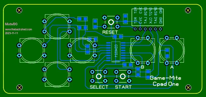
| Mixtel90 Guru Joined: 05/10/2019 Location: United KingdomPosts: 6792 |
... and a nice little accessory for it. :)  EDIT: Another possibility - a NES controller adapter. Edited 2023-11-11 19:12 by Mixtel90 Mick Zilog Inside! nascom.info for Nascom & Gemini Preliminary MMBasic docs & my PCB designs |
||||
| Martin H. Guru Joined: 04/06/2022 Location: GermanyPosts: 1113 |
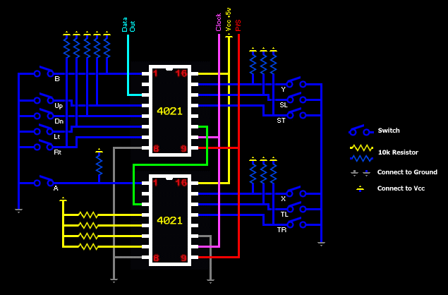
so for SNES, just the Output changes from 1 to 2 Bytes so the software has to read 16 Bit  Edited 2023-11-12 02:09 by Martin H. 'no comment |
||||
| Mixtel90 Guru Joined: 05/10/2019 Location: United KingdomPosts: 6792 |
That's correct. That's the very same circuit I've been looking at. :) Instead of resetting Latch after 8 clock pulses you reset it after 16. Mick Zilog Inside! nascom.info for Nascom & Gemini Preliminary MMBasic docs & my PCB designs |
||||
| thwill Guru Joined: 16/09/2019 Location: United KingdomPosts: 4040 |
Actually I think you can reset after 12 since there are 4 unused lines. Best wishes, Tom Game*Mite, CMM2 Welcome Tape, Creaky old text adventures |
||||
| Mixtel90 Guru Joined: 05/10/2019 Location: United KingdomPosts: 6792 |
I'm not sure, but I think the original idea was to always run 16 clocks and just ignore the returned bits that you don't need. It's something I saw mentioned somewhere. It allows for any future expansion of the controllers (up to 16 bits, obviously). So s SNES controller would work on a NES (after a fashion) and vice versa. Mick Zilog Inside! nascom.info for Nascom & Gemini Preliminary MMBasic docs & my PCB designs |
||||
| Volhout Guru Joined: 05/03/2018 Location: NetherlandsPosts: 4237 |
Hi Mick, The boards are ordered (5 pieces). This is what I am planning to ship to David as a kit for his channel, pre-loaded with the PETSCII ROBOTS... Now I have to gather the parts. Thanks for providing a parts list. Very helpfull... Thank you for your help. Volhout PicomiteVGA PETSCII ROBOTS |
||||
| Mixtel90 Guru Joined: 05/10/2019 Location: United KingdomPosts: 6792 |
If I've figured the connector out right, here's a version 2, which includes a WII controller connection. Edited 2023-12-16 02:08 by Mixtel90 Mick Zilog Inside! nascom.info for Nascom & Gemini Preliminary MMBasic docs & my PCB designs |
||||
| Hawk Senior Member Joined: 15/07/2021 Location: AustraliaPosts: 141 |
It looks very compact. I know that you enjoy the art of PCB design, but I was wondering what your goals are for this design? Is it sized to fit a particular case? Is there a particular use case you are trying to solve. Is the compactness of the PCB to keep the cost down? The reason that I ask, I have the Silicon Chip design without any audio. It’s in the custom 3D printed case published in this forum. It meets most of my design requirements except for the following: - no audio - no joystick - no reset button mounted on rear - no power switch on rear - no power LED on front - no expansion for RTC Now I know that when it was published, some of the goals would have been cost and simplicity. They’re important if you’re planning to make lots of them or use them as an educational activity. But for a deluxe model, those factors are not so important. Then there’s the whole discussion about the form factor. Where is it intended to sit on your desk. Does it sit flat beside your monitor? Is it wide enough to sit under your monitor? Do you make a vertical stand for it to take up less desk space? In this case, which cables are heavier and more likely to pull the case over? Do cables come out of the case from everywhere, taking up more desk space, or only from the back? Do you mount it on the back of your monitor, and only have the keyboard cable coming across your desk? Anyway, I love that you continue to evolve the PCB design, I was just interested in you goals. |
||||
| Volhout Guru Joined: 05/03/2018 Location: NetherlandsPosts: 4237 |
Hi Hawk, When the silicon chip design was published, there was no software that could do audio. There is an expansion connector, so you can add all the above. But, I like the fact that the board is designed to fit in a case That is the reason that I use Peters 1.7 VGA design as my main workhorse. It has all you mention, except the rear side reset switch and the joystick. But there is a reset switch. It fits the same case as the CMM2 (did not check but probably also the CMM1, since the boards are very similar in size) Volhout P.s. the joystick interface on pico is not settled yet. There is Wii Classic, SNES,NES, all having different connectors. Mick has added Wii Classic to this mini design. P.P.S. Mick, the gerbers of V2, are they available somewhere ? Edited 2023-12-17 18:42 by Volhout PicomiteVGA PETSCII ROBOTS |
||||
| Mixtel90 Guru Joined: 05/10/2019 Location: United KingdomPosts: 6792 |
I'll sort the gerbers out for you. Probably later today. :) This particular design (version 1) was to get sufficient on the board to be able to play games using the keyboard. It also had to be easy to build. No case was considered necessary as it's primarily a basic "hacker's" system. I kept the connections sensible (I think) so that a simple 3D printed case might be possible. The expansion connector includes 3V3, GND, GP26, GP27 & GP28 so there is enough to implement I2C controllers, NES controllers or analogue paddles. I've added a second expansion on V2, which gas 3V3, GND, GP0, GP1 & GP2. That would allow a controller of some sort while using the original expansion for a RTC. If you want a nice, cased games box then there are others, including my PicoGAME designs which all fit the same Hammond enclosure (in "computer grey", black or a rather cool translucent blue!). You will always pay for a decent case though and it puts some people off. I had trouble in obtaining the CMM2 case at one time, the Hammond was easier and, believe it or not, cheaper to get. It also takes a 100mm x 100mm board nicely, which is available at a very cheap price from JLCPCB. :) I'm just waiting for some WII connectors to test it with before I release PicoGAME version 4. Mick Zilog Inside! nascom.info for Nascom & Gemini Preliminary MMBasic docs & my PCB designs |
||||
| Page 1 of 2 |
|||||