|

|
Forum Index : Microcontroller and PC projects : Just testing a Game-Mite concept
| Page 1 of 2 |
|||||
| Author | Message | ||||
| Mixtel90 Guru Joined: 05/10/2019 Location: United KingdomPosts: 6798 |
Peter commented that you couldn't sensibly get buttons below the 3.2" display using 100mm square PCB.so, being the awkward old goat that I am, I had to try it. :) I ended up having to lower them by 1.27mm. Apart from that (and moving the Reset button a bit) the buttons are in the same places as they are on Tom & Mick's design. I've cheated horribly because the PicoMite hasn't enough GPIO so the buttons are on an I2C expander. Consequently this isn't Game*Mite compatible and I can't make it so. It's merely a concept to see what would fit where. I've no display so I can't get an exact thickness or anything. Treat it as a pretty picture. :) Mick Zilog Inside! nascom.info for Nascom & Gemini Preliminary MMBasic docs & my PCB designs |
||||
| thwill Guru Joined: 16/09/2019 Location: United KingdomPosts: 4042 |
LOL This is 95% the Game2Mite that I was going to prototype next year and if anyone cared (given Peter's SMD offering) that I was going to ask @bigmik to design a PCB for. Differences: 1. I was going to use a shift-register with 10K resistor array as an IO expander; 74hc165 or cd4021 2. I was going to fit a push-push uSD card 3. I was only going to use a single-speaker and PAM8302 mono-amplifier It will be a minor update to support two (or more) different controller configurations. I'm intending to read the controller configuration from a csv file: A:/.config or A:/.spconfig. Best wishes, Tom Edited 2023-10-31 00:17 by thwill Game*Mite, CMM2 Welcome Tape, Creaky old text adventures |
||||
| Mixtel90 Guru Joined: 05/10/2019 Location: United KingdomPosts: 6798 |
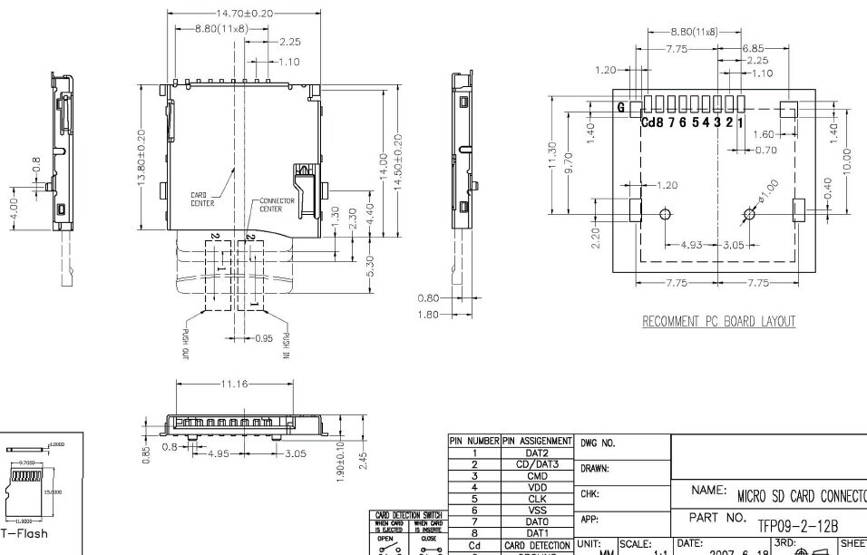
I wasn't intending to predict the future. :) It was a toss-up which way to go on the controls. I2C has a slight advantage, I think, in that you don't need to keep polling them, an interrupt is triggered whenever a button is pressed. OTOH the software to initialise it is more complicated. The difference in cost isn't all that much. The interrupt need only set a flag and the buttons handled during frame flyback only if they need to be. I looked for a suitable push-push uSD card holder but could only find dimensional drawings of "proper" ones, not the cheap ones from ebay/AE. Mind you, I didn't search for very long. I'm sure there's something around. I just didn't bother with speakers. I figured that lo-fi headphones are perfectly fine - and save all the complaints from other people on public transport! I've not actually tested this audio arrangement. It should work in theory, I think. Only 1/2 of each amp is actually used so the output power is much less. May be perfectly fine for headphones though. Mick Zilog Inside! nascom.info for Nascom & Gemini Preliminary MMBasic docs & my PCB designs |
||||
bigmik Guru Joined: 20/06/2011 Location: AustraliaPosts: 2914 |
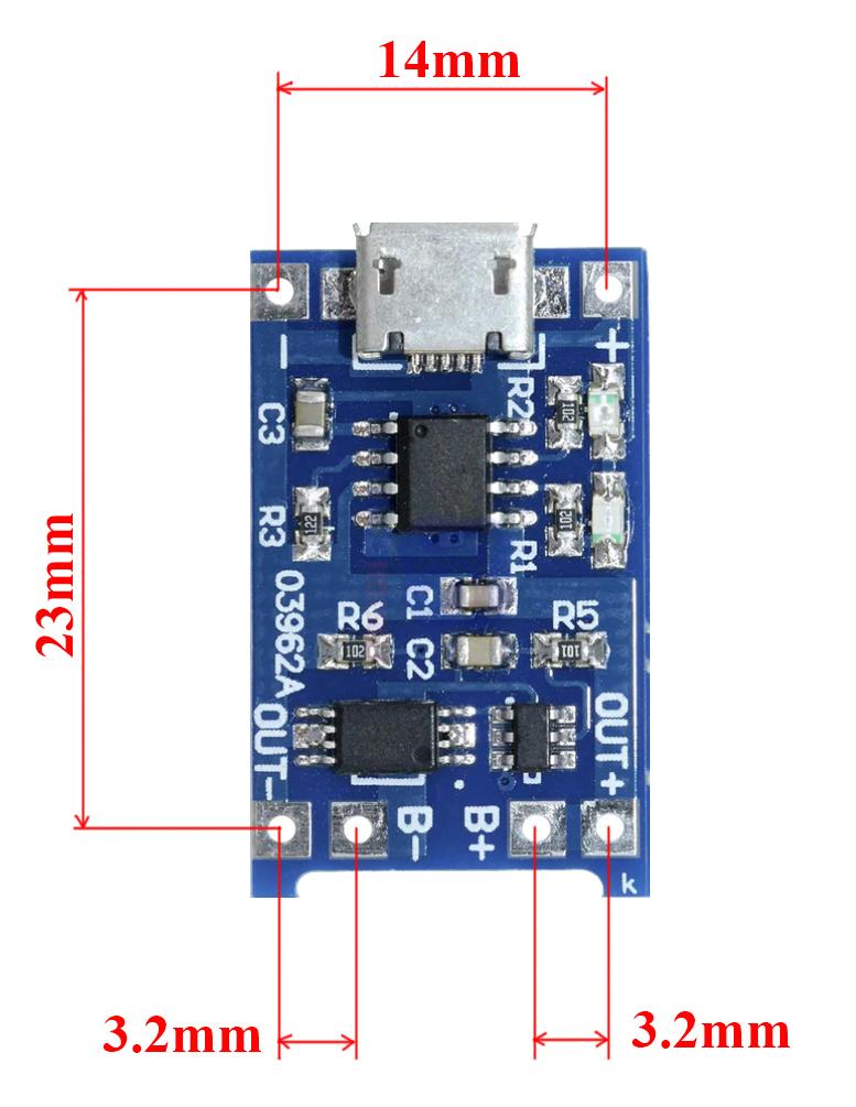
Hi Mick, All, Check the pin spacing on the TP4056 module. Specifically the output and Batt connections. You seem to have them on 2.54mm spacing, they are actually around 3.5mm. I can give you the exact sizing later today if you want them. You seem to have the OUT and IN correct it is actually the B+ and B- that are too close to OUT+ and OUT- Regards, Mick Edited 2023-10-31 08:14 by bigmik Mick's uMite Stuff can be found >>> HERE (Kindly hosted by Dontronics) <<< |
||||
bigmik Guru Joined: 20/06/2011 Location: AustraliaPosts: 2914 |
Hi Mick, All, I see the keypad is raised by 5mm spacers.. how do you intend to connect the 2 PCBs ? Normally the gap between the 2 PCBs would be 11mm if using standard male/female header pins. Regards, Mick Mick's uMite Stuff can be found >>> HERE (Kindly hosted by Dontronics) <<< |
||||
Grogster Admin Group Joined: 31/12/2012 Location: New ZealandPosts: 9308 |
Simple wire links perhaps? IE: Mount the PCB on the spacers, feed tin-plated copper wire through the top and bottom PCB holes and solder. That was a very common method in the past, before they started socketing everything.  Smoke makes things work. When the smoke gets out, it stops! |
||||
| Mixtel90 Guru Joined: 05/10/2019 Location: United KingdomPosts: 6798 |
Thanks Mick, I'll check the TP4056. I don't know where I got the measurements now. I had wire links in mind for the keypad. There's nothing underneath it that would require future access so a plug and socket would be a bit of a waste. I'm not sure of the height - I think it probably needs to be 1 or 2mm higher. That would need finalising with a display in place. Mick Zilog Inside! nascom.info for Nascom & Gemini Preliminary MMBasic docs & my PCB designs |
||||
bigmik Guru Joined: 20/06/2011 Location: AustraliaPosts: 2914 |
GDay Mick, All, I have checked the hole spacings and I am right that they are NOT 2.54mm but they are actually 3.2mm. See this size guide I made up. Note! This is true for the modules that I have fitted with micro-USB connectors, I can't guarantee that other varieties of the TP4056 module are the same.  I hope this helps. Regards, Mick Mick's uMite Stuff can be found >>> HERE (Kindly hosted by Dontronics) <<< |
||||
| Mixtel90 Guru Joined: 05/10/2019 Location: United KingdomPosts: 6798 |
Oh, excellent! I'll update my makro now. :) Mick Zilog Inside! nascom.info for Nascom & Gemini Preliminary MMBasic docs & my PCB designs |
||||
| thwill Guru Joined: 16/09/2019 Location: United KingdomPosts: 4042 |
FYI the modules I have with USB-C connector have the same pin positioning; or at least the holes on @bigmik's Game*Mite PCBs match my modules. Other than that they are pretty much of identical appearance except for using much smaller SMD resistors and capacitors, including for R3 which is supposed to be user replaceable :-( Best wishes, Tom Game*Mite, CMM2 Welcome Tape, Creaky old text adventures |
||||
| Mixtel90 Guru Joined: 05/10/2019 Location: United KingdomPosts: 6798 |
Fixed the footprint of the charger. Thanks Mick! Can now do a CD4021 and resistors, no problem. The resistors (if they are really needed) have plenty of space in the gap below the buttons PCB. For some reason the I2C expander chip seems very expensive on ebay. Mick Zilog Inside! nascom.info for Nascom & Gemini Preliminary MMBasic docs & my PCB designs |
||||
| Mixtel90 Guru Joined: 05/10/2019 Location: United KingdomPosts: 6798 |
I've changed the buttons PCB to make it, to all intents and purposes, a NES controller in its own right. Using SMD and linking it via flexible wires means that the front has no tracks or component holes other than for the buttons themselves. I think it's kinda pretty. :) I've also found a push-push uSD card socket that's readily available all over, including ebay and AE. Proper drawings are available too. The part number is PJS008-2130=0 It's bigger than the push-pull one that I've used previously and is more difficult to run traces to as there is a big no-go area. Mick Zilog Inside! nascom.info for Nascom & Gemini Preliminary MMBasic docs & my PCB designs |
||||
| thwill Guru Joined: 16/09/2019 Location: United KingdomPosts: 4042 |
Hi Mick, Am I correct that the controller is connected to the main PCB by flying wires soldered to the pads on the right of the controller PCB ? It looks like the RESET, SELECT and START buttons could now be correctly centered fairly easily ? FYI the push-push uSD sockets that I've just received for retro-fitting to my personal Game*Mites are these: https://www.aliexpress.com/item/1005004571249841.html  Best wishes, Tom Game*Mite, CMM2 Welcome Tape, Creaky old text adventures |
||||
| Mixtel90 Guru Joined: 05/10/2019 Location: United KingdomPosts: 6798 |
IMHO it looks odd if you centre Select and Start. Centering Reset above them works well though. Looks like your uSD card holder is the opposite of mine, which has the solder contacts on the outer edge of the PCB - like my push-pull one. There's nothing like a bit of standasation. :) Mick Zilog Inside! nascom.info for Nascom & Gemini Preliminary MMBasic docs & my PCB designs |
||||
| Mixtel90 Guru Joined: 05/10/2019 Location: United KingdomPosts: 6798 |
And now a big turnaround. Rearranged to do the following: Surface mount he Pico - no point in having 40 pins that have to be cropped down. This also reduces its height from the PCB surface. Put the components on the bottom of the PCB, using the space under the display for the battery and stereo speakers. Use a switched headphone jack socket. Move the (push-push) SD card socket and power switch to the front. Allow an option for the backlight to be dimmable. Mick Zilog Inside! nascom.info for Nascom & Gemini Preliminary MMBasic docs & my PCB designs |
||||
| stanleyella Guru Joined: 25/06/2022 Location: United KingdomPosts: 2129 |
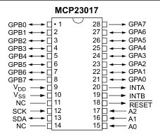
I'm building a button pad using mcp23017. grounds wired just get dil right for wiring. i2c must be as good as vga keyboard?? |
||||
| Turbo46 Guru Joined: 24/12/2017 Location: AustraliaPosts: 1611 |
Stan, Please note that for later versions of that chip the I/O arrangement has changed. GPA7 and GPB7 are output only. You may have to use two ports if you have eight switches.  A CD4021 with a resistor array needs no setup and Tom has code for the NEC controller that works well. Bill Keep safe. Live long and prosper. |
||||
| Mixtel90 Guru Joined: 05/10/2019 Location: United KingdomPosts: 6798 |
The 4021 is *far* simpler to use, and a lot cheaper too. :) The Game*Mite games won't work with the I2C system at the moment. Edited 2023-11-04 05:57 by Mixtel90 Mick Zilog Inside! nascom.info for Nascom & Gemini Preliminary MMBasic docs & my PCB designs |
||||
| thwill Guru Joined: 16/09/2019 Location: United KingdomPosts: 4042 |
Is there any reason to favour a CD4021 over a 74HC165 or vice versa? I believe I read somewhere that the 4000 series CMOS wasn't rated for use as low as 3v3, though it has worked for me. Best wishes, Tom Edited 2023-11-04 06:38 by thwill Game*Mite, CMM2 Welcome Tape, Creaky old text adventures |
||||
| Turbo46 Guru Joined: 24/12/2017 Location: AustraliaPosts: 1611 |
On the data sheets that I have seen: 74HC165 operates from 2 to 6 volts CD4021 operates from 5 to 20 volts So operating the CD4021 at 3v3 is probably not a good idea for absolute reliability. Also, for the 74HC165, the minimum load pulse with 2v supply is 100nS so I think it is the better choice all round. Bill Keep safe. Live long and prosper. |
||||
| Page 1 of 2 |
|||||