
|

|
Forum Index : Microcontroller and PC projects : [PicoMite] count input on rising edge PROBLEM, no it's not me!
| Page 1 of 2 |
|||||
| Author | Message | ||||
| Amnesie Guru Joined: 30/06/2020 Location: GermanyPosts: 396 |
Hello dear people, it's me again... I've encountered a problem with: Option Explicit Dim Integer int=4 Dim Integer count SetPin int, cin, 2 'set pin(GP2) for count input on rising edge Do count=pin(int) Print count Loop PROBLEM: 1 count is always 2 counts. I know what you think: "how does the pulse look like, and do you have the correct trigger (falling edge)?" My triggering is ok and the pulse is isolated, there is just one pulse and it always counts 2 instead of 1 (as it should). The application is my own Geiger Counter. And the pulse is at nice clean logic level thanks to the 74HC14 IC. Scope: 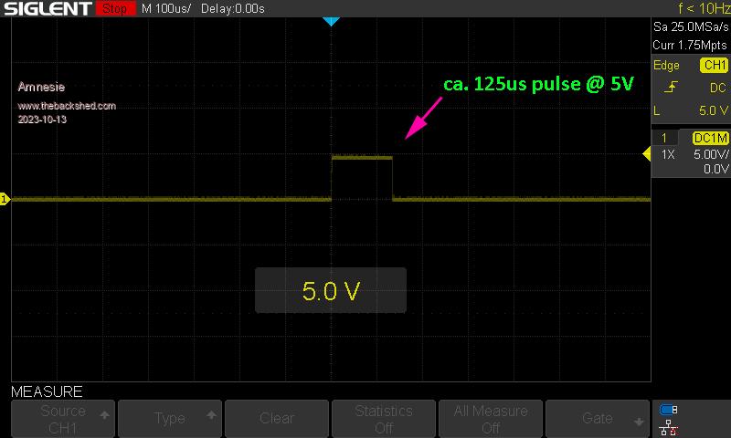 Result & Options: 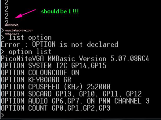 My assumption is: The pulse of around 125us is too short for the pico, so it always counts 2 instead of 1. What do you think? Greetings Daniel |
||||
| matherp Guru Joined: 11/12/2012 Location: United KingdomPosts: 9123 |
It is possibly an artifact of the transition from a floating pin to an input Try this and see if it fixes Option Explicit Dim Integer int=4 Dim Integer count SetPin int, cin, 2 'set pin(GP2) for count input on rising edge pause 100 pin(int)=0 Do count=pin(int) Print count Loop |
||||
| Amnesie Guru Joined: 30/06/2020 Location: GermanyPosts: 396 |
Hello Peter, sadly it does not fix it. I've tried it again with your suggestion and without. I've noticed that it isn't always exactly 2 instead if 1 count event, but some times even 3 or 4, but most of the time it's 2... The strange thing is: with my other geiger circuit everything is fine. But there the pulse is longer, that's why I thought my be the pulse is "too short". (just to be clear: I've hooked up my scope in parallel und can verify that there are NOT more pulse, so something is wrong with the counting on the pico...) Greetings Danie Edited 2023-10-13 00:35 by Amnesie |
||||
| matherp Guru Joined: 11/12/2012 Location: United KingdomPosts: 9123 |
Is it the same if you use another pin as the input? Why are you using option 2? Try without the 2. Your pulse is rising not falling Setting 2 applies a pullup and looks for a falling edge. If the geiger is driving low then that immediately creates a count without a pulse Edited 2023-10-13 00:44 by matherp |
||||
| Amnesie Guru Joined: 30/06/2020 Location: GermanyPosts: 396 |
Yes, its the same problem. If I use 1 (specifies a rising edge) It not only doubles the counts but takes it times four. so instead of 1 real count event I have 4 most of the time. Of course you are right, 1= rising edge is correct , I just changed it back because this makes it even worse... Edited 2023-10-13 00:50 by Amnesie |
||||
| matherp Guru Joined: 11/12/2012 Location: United KingdomPosts: 9123 |
did you see this Why are you using option 2? Try without the 2. Your pulse is rising not falling Setting 2 applies a pullup and looks for a falling edge. If the geiger is driving low then that immediately creates a count without a pulse |
||||
| Volhout Guru Joined: 05/03/2018 Location: NetherlandsPosts: 4244 |
Maybe I am mistaken, but you drive the 3.3V pico input pin with 5V ? Volhout PicomiteVGA PETSCII ROBOTS |
||||
| Amnesie Guru Joined: 30/06/2020 Location: GermanyPosts: 396 |
with: 1 specifies a rising edge, 2 a falling edge and 3 specifies that both edges should be counted observations: (real count of 1) I get with the pico: Option 1: most of the time 2-3 counts Option 2: most of the time 2-3 counts Option 3: most of the time 4 counts |
||||
| Amnesie Guru Joined: 30/06/2020 Location: GermanyPosts: 396 |
Hello Volhout you are correct. I am driving it with 5V and there are many sources which say this is no problem at all, in fact I already done this with exactly this pin & device (+ others) for a long time. The point is: with my other geiger circuit (which has a longer pulse and 5V, too!) everything works fine. So my assumption is the pulse is too short for the pico and I thought Peter could confirm this by posting a theoretical maximum or something. Now I am trying to stretch the pulse on my geiger, but this is a bad option since I want maximum counting speed for high doses of radiation. Edited 2023-10-13 01:01 by Amnesie |
||||
| matherp Guru Joined: 11/12/2012 Location: United KingdomPosts: 9123 |
CIN works perfectly with a 100uS pulse created by the PULSE command. As Volhout notes if you are using 5V input then all bets are off (including whether the Pico will ever work properly again) The minimum pulse width for CIN is probably a few tens of nanoseconds Edited 2023-10-13 01:03 by matherp |
||||
| Amnesie Guru Joined: 30/06/2020 Location: GermanyPosts: 396 |
Peter this is interesting I am not ignoring your suggestions! what I've done now: taking a clean non used ever before pico (fresh out of the box) and quickly put a level shifter to 3v3 volts in between. Same problem. BUT: As I wrote in my previous post: I now have modified my geiger circuit to strech the pulse. And guess what happend? Everything works fine @ 5V and 3v3 logic. So my initial assumption is right. But for me it doesn't stop there, because you said: I must understand why this happens. So I am checking now with my scope how long the pulse with my streched and modified geiger circuit is. To verify at which point the pico can't deal with it. After that I am connecting my Siglent Wave Form Generator (yes I know I should have done this earlier...). But now I want to know how far I can REALLY push the pico.   |
||||
| Mixtel90 Guru Joined: 05/10/2019 Location: United KingdomPosts: 6798 |
Does it work with a GPn number instead of using the variable "int"? Just clutching at straws. I suspect that to get the fastest response from the Pico you'll have to use the interrupt form: SETPIN pin, cfg, target [.option] where, I think, the interrupt is a hardware one. Edited 2023-10-13 01:21 by Mixtel90 Mick Zilog Inside! nascom.info for Nascom & Gemini Preliminary MMBasic docs & my PCB designs |
||||
| matherp Guru Joined: 11/12/2012 Location: United KingdomPosts: 9123 |
No, other way round. CIN, PER, and FIN are H/W the others are software polled at the end of every statement |
||||
| matherp Guru Joined: 11/12/2012 Location: United KingdomPosts: 9123 |
Sounds like it could be an earthing/ringing problem between the geiger and the Pico. Can't see any other reason why you would get multiple counts as the Pico just uses an edge triggered H/W interrupt. Missed counts I could understand but multiple must be electrical. Just to satisfy me why not connect two Pico. On one use PULSE pin,0.001 to generate a 1uS pulse and on the other use the CIN command to read it |
||||
| Amnesie Guru Joined: 30/06/2020 Location: GermanyPosts: 396 |
Mick, I am trying your suggestion too. Now what I've done so far (solved the problem but leaves question marks) I thought with this modification I would "stretch" the pulse, but the scope says it's about 125us (like before). Schematic: 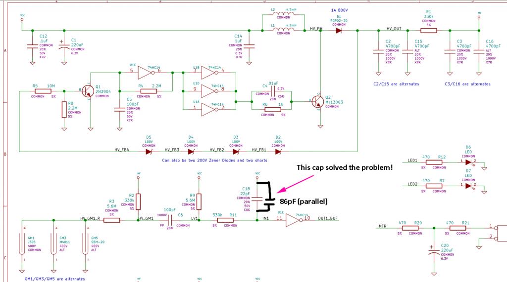 (I soldered a 86pF cap in parallel) At "OUT1_BUF" is the pico connected. If the pulse length is the same, can anyone tell my why this solved the problem?! Edited 2023-10-13 01:42 by Amnesie |
||||
| Mixtel90 Guru Joined: 05/10/2019 Location: United KingdomPosts: 6798 |
Thanks Peter. I've made a note in my manual. :) erm... no. 74HC14 is a Schmitt trigger so its output shouldn't change much, I don't think. Edited 2023-10-13 01:54 by Mixtel90 Mick Zilog Inside! nascom.info for Nascom & Gemini Preliminary MMBasic docs & my PCB designs |
||||
| matherp Guru Joined: 11/12/2012 Location: United KingdomPosts: 9123 |
Take the cap off and then zoom in on the leading and falling edges of the pulse if your scope is fast enough. The Pico will probably trigger on anything longer than about 2/133MHz = 15nSec |
||||
| Amnesie Guru Joined: 30/06/2020 Location: GermanyPosts: 396 |
Hello Peter, I've done some measurements but can't really tell a difference. I comparead in real time with the pico reading, the scope was parallel. In every case the count SHOULD BE 1, not more. 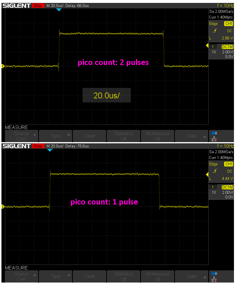 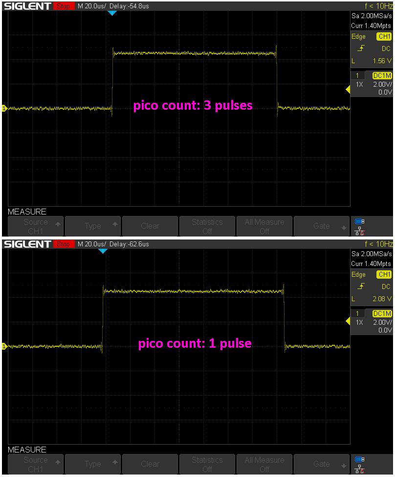 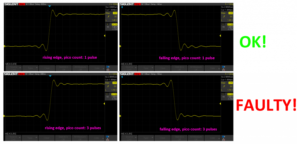 |
||||
| Amnesie Guru Joined: 30/06/2020 Location: GermanyPosts: 396 |
Finally I found the main problem and I hope you can lern from my dumb ideas....  First of all: Peter must have been right (like in 99,9% of cases) something "confused" the pico, on the count pin my scope was attached I cannot see anything strage (se post above).. there must be some noise or interference, ringing whatever.. so I took a close look at my schematic and measured at collector of transistor Q3 of my own drawing: 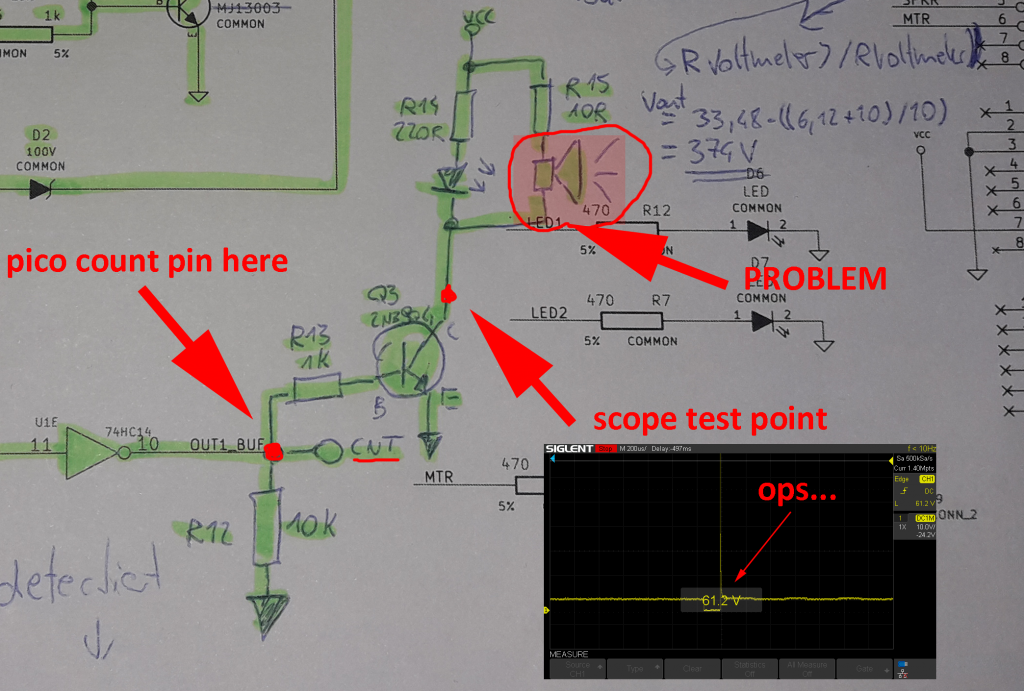 closer look at scope: 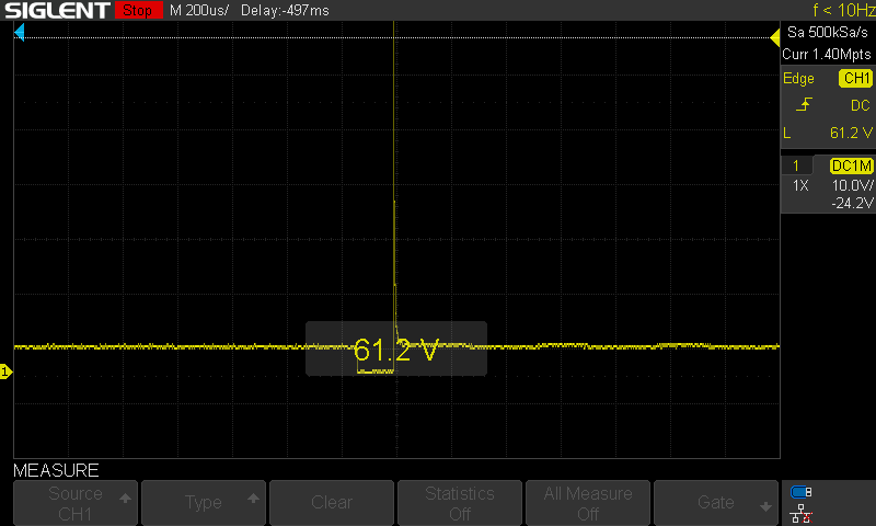 Problem part is the buzzer, when active (and only when active!) there are transients way above 50 volts at collector of Q3! This causes the problem, this is the root of all evil. By disconnecting the buzzer (not a piezo one!) no parallel capacitor needed and no double countings anymore. Since this is an inductor it explains this peak in voltage and it may send and interfere with the pico. Problem solved. Maybe someone find this entertaining, at least I am a bit wiser now   Greetings and thank you all for suggestions! Daniel |
||||
| Mixtel90 Guru Joined: 05/10/2019 Location: United KingdomPosts: 6798 |
Wow.... What's VCC? Have you tried a simple reverse diode from collector to VCC? Mick Zilog Inside! nascom.info for Nascom & Gemini Preliminary MMBasic docs & my PCB designs |
||||
| Page 1 of 2 |
|||||