|

|
Forum Index : Microcontroller and PC projects : 4-20mA loop to 0.64-3.2V for ADC
| Page 1 of 2 |
|||||
| Author | Message | ||||
| DrifterNL Regular Member Joined: 27/09/2018 Location: NetherlandsPosts: 58 |
Hello all, Is my thinking correct? If I want to read out a sensor (that needs 12V) with an output of 4 - 20mA and convert that into 0.64 to 3.2V for an ADC on the Pico, all I would need is a 160Ω resistor between the output and common gnd? And would it be a good idea to place a capacitor between adc and gnd to filter out any interference (voltage spikes) to protect the pico adc port? Floating Point Keeps Sinking Me! Back To Integer So I Don't Get Injured. |
||||
| ryanm Senior Member Joined: 25/09/2015 Location: AustraliaPosts: 202 |
To measure current you'll need to measure the voltage drop across a resistor in series, this is generally done with an op-amp front end circuit. If you're just working on a one off you can pick up a pre-made circuit board for about $5 that will do this for you. |
||||
| phil99 Guru Joined: 11/02/2018 Location: AustraliaPosts: 2136 |
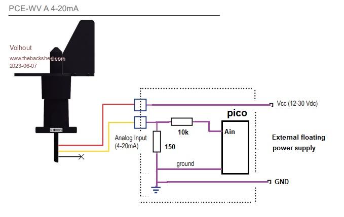
That can work provided there is no other link between the Pico and the sensor. Use a "floating" or isolated power supply for the sensor with no ground-to-ground link to the Pico, just the 2 20mA loop wires. |
||||
| Mixtel90 Guru Joined: 05/10/2019 Location: United KingdomPosts: 6798 |
It's advisable to give the Pico input some protection just in case the current sensing resistor goes open circuit. The Pico input needs very little current so a series resistor of up to 10k then a 3V3 to 3V5 zener to GND is fine if you are only expecting up to 3V2. It would also be a good idea to put a reverse parallel diode across the current sense resistor as the Pico input won't accept reverse voltage. As Phil says, you will have to watch where your GND lines are. Mick Zilog Inside! nascom.info for Nascom & Gemini Preliminary MMBasic docs & my PCB designs |
||||
| DrifterNL Regular Member Joined: 27/09/2018 Location: NetherlandsPosts: 58 |
The device I'm looking into is the PCE Instruments PCE-WV A 4-20mA. Link to Manual The problem is I would like to connect the wind vane and Pico(with a buck converter) to one 12V power source. If not feasible I'll keep searching for another wind vane. Floating Point Keeps Sinking Me! Back To Integer So I Don't Get Injured. |
||||
| Volhout Guru Joined: 05/03/2018 Location: NetherlandsPosts: 4247 |
This should work...  Edited 2023-06-07 19:41 by Volhout PicomiteVGA PETSCII ROBOTS |
||||
| DrifterNL Regular Member Joined: 27/09/2018 Location: NetherlandsPosts: 58 |
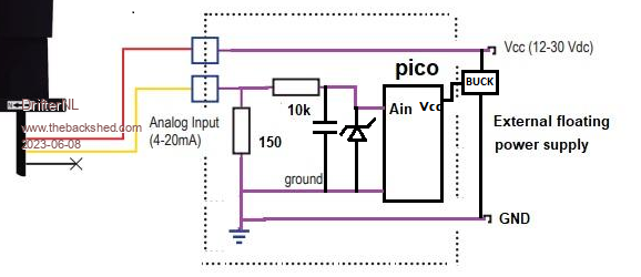
So with all the info put together something like this?  Edited 2023-06-08 05:03 by DrifterNL Floating Point Keeps Sinking Me! Back To Integer So I Don't Get Injured. |
||||
| Volhout Guru Joined: 05/03/2018 Location: NetherlandsPosts: 4247 |
Personally I would not place the zener there, but accross the 150 ohm resistor,, or not at all. Low voltage zeners have high leakage current, that depends on the applied voltage. This will cause large linearity faults. So I would remove the zener completely, and rely on the 10k resistor to keep the pico pin intact. Volhout Edited 2023-06-08 05:08 by Volhout PicomiteVGA PETSCII ROBOTS |
||||
| Mixtel90 Guru Joined: 05/10/2019 Location: United KingdomPosts: 6798 |
Yes, that looks ok to me. What you have labelled as a buck regulator could be a linear regulator if you don't mind a little heat. A PicoMite doesn't draw a lot of current (unless you are also running a LCD display with backlight). A switching regulator runs almost cold and you could use a 3V3 output version and disable the on-board switcher. Watch your input voltage as most regs (of all sorts) quote 30V as absolute maximum. That can be exceeded by a 24V battery that's on charge. Mick Zilog Inside! nascom.info for Nascom & Gemini Preliminary MMBasic docs & my PCB designs |
||||
Quazee137 Guru Joined: 07/08/2016 Location: United StatesPosts: 571 |
For my DinRail controllers I use these B0512S-1W they come in so many useful voltages inputs and outputs can be used. I use the 5VDC in and 12VDC out for my PH boards Quazee137 On a few 4-20mA loops I use a 5VDC in and 24VDC out to power the loop. I do use resettable fuses of 50mA feeding the loop. Edited 2023-06-08 06:55 by Quazee137 |
||||
| DrifterNL Regular Member Joined: 27/09/2018 Location: NetherlandsPosts: 58 |
Thanks all! I'm going to order one and give it a try. I'm just confused as to yes or no to the Zener. Floating Point Keeps Sinking Me! Back To Integer So I Don't Get Injured. |
||||
| Mixtel90 Guru Joined: 05/10/2019 Location: United KingdomPosts: 6798 |
The zener doesn't do anything unless the sense resistor goes open circuit for some reason. If that happens it will clamp the voltage down to a safe level so that the PicoMite doesn't get damaged. It's optional, especially if you use a sense resistor that can never be overloaded. I'm not sure what voltage you are using, so I'll guess at 24v. If the transmitter goes short circuit then the sense resistor will carry 24/150 = 0.16A. The power dissipated will be 0.16*0.16*150 = 3.8W and the voltage across it will be 24V, of course. That's quite a big resistor you have to fit - wire wound so probably not close tolerance unless it's expensive. On the other hand you could use a 150R resistor of a much lower rating (say 250mW as maximum normal dissipation is only 60mW) and let it burn out. A zener will then keep the Pico safe while the resistor goes open circuit. Ideally it should be a fusible resistor for this job. All this is only a problem if the transmitter starts to pass way too much current. It probably won't do it for long but you never know. Or someone may accidentally short circuit the terminals while the power is on (It's only 24v. It won't hurt me. :) ) at some time in the future. Mick Zilog Inside! nascom.info for Nascom & Gemini Preliminary MMBasic docs & my PCB designs |
||||
| Volhout Guru Joined: 05/03/2018 Location: NetherlandsPosts: 4247 |
Mick, the zener must be parallel to the 150 ohm resistor when used. Not at the adc pin. The 10k will cause problems. The zener could easily leak 1 mA at 3 volt. Try it.... you will have these parts in your lab... Edited 2023-06-09 08:41 by Volhout PicomiteVGA PETSCII ROBOTS |
||||
| phil99 Guru Joined: 11/02/2018 Location: AustraliaPosts: 2136 |
The supply is 12V so worst-case dissipation is 960mW. Standard 1W resistor will do. As previously noted below 4V7 zenners are not ideal. Leave out the zenner and put a schottky diode from AIN to 3V3. Cathode to 3V3. The 10k will limit the worst-case current through it to less than 1mA. |
||||
| DrifterNL Regular Member Joined: 27/09/2018 Location: NetherlandsPosts: 58 |
Hi all, Came across this and just wondering if this would work. SEN0262 Gravity Analoge Current to Voltage Converter Floating Point Keeps Sinking Me! Back To Integer So I Don't Get Injured. |
||||
| Mixtel90 Guru Joined: 05/10/2019 Location: United KingdomPosts: 6798 |
It certainly will work. It's a good design. There is plenty of protection for the PicoMite and, indeed, the op-amp input. A good idea if the leads are long, particularly if they are running outside for any distance. Incidentally, the TVS diodes protecting the inputs are like 24V bi-directional zeners and R2 and R5 are resettable 500mA fuses. Note that the analogue inputs on the PicoMite are not very good and you won't get good linearity. There's no work-around other than use a separate A-D converter. By all means try it first and see if the results are acceptable. Edited 2023-06-12 17:32 by Mixtel90 Mick Zilog Inside! nascom.info for Nascom & Gemini Preliminary MMBasic docs & my PCB designs |
||||
| DrifterNL Regular Member Joined: 27/09/2018 Location: NetherlandsPosts: 58 |
Just a quick update. I have the wind vane connected to the PicoMite through the SEN0262, test software up and running and all works great. Edited 2023-07-19 07:21 by DrifterNL Floating Point Keeps Sinking Me! Back To Integer So I Don't Get Injured. |
||||
| Volhout Guru Joined: 05/03/2018 Location: NetherlandsPosts: 4247 |
Hi Drifter, Thanks for the update. It is really appreciated. Sometimes you provide help, and in the end never know if it really helped someone or not It just confused...). Good luck with your project, Volhout Edited 2023-07-19 18:42 by Volhout PicomiteVGA PETSCII ROBOTS |
||||
| DrifterNL Regular Member Joined: 27/09/2018 Location: NetherlandsPosts: 58 |
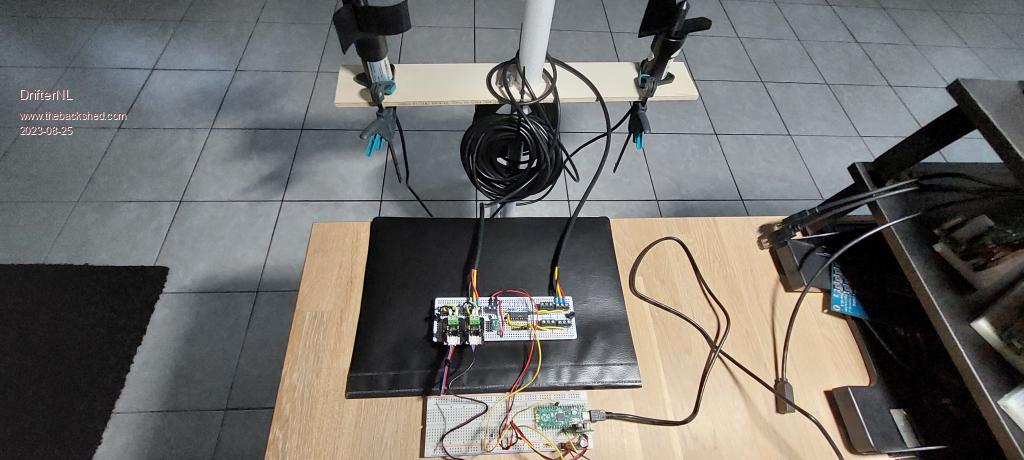
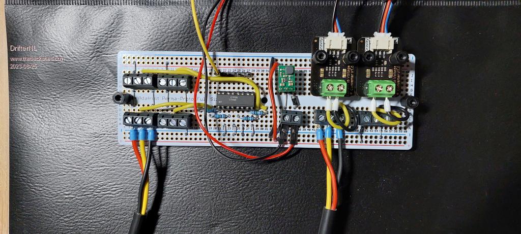
Another update: Here is my connection board for hooking up the wind vane and anemometer. It's made on one of those Adafruit perma-proto boards. I might get around to designing a proper PCB in the future. The anemometer (PCE Instruments PCE-WS P) is connected to the PicoMite through an optocoupler (LTV847) and the wind vane (PCE Instruments PCE-WV A) through a current to voltage module (DFRobot / Gavity SEN0262). Because I want to use one power supply it also has an 12V boost regulator (Pololu U3V16F12). Oh, and just to make sure I didn't mess up, I tested the board on my battle damaged Pico (On another project I lost two ports when I accidentally took out the wrong resistors on a voltage devider, they got the full 12V treatment and on another project I messed up with and oscilloscope and shorted the Pico 3.3V regulator to GND. Fun Times!) I'll probably start a new thread about my Wireless Weather Station project.   Edited 2023-08-25 03:31 by DrifterNL Floating Point Keeps Sinking Me! Back To Integer So I Don't Get Injured. |
||||
| Mixtel90 Guru Joined: 05/10/2019 Location: United KingdomPosts: 6798 |
Shorting the 3V3 to GND for a short period doesn't usually cause damage. It just causes the switcher to shut down, I think. I must admit, I've not tried it. :) Nice setup! :) Mick Zilog Inside! nascom.info for Nascom & Gemini Preliminary MMBasic docs & my PCB designs |
||||
| Page 1 of 2 |
|||||