|

|
Forum Index : Microcontroller and PC projects : chage pins for SPI or SD-Card
| Page 1 of 2 |
|||||
| Author | Message | ||||
| hhtg1968 Senior Member Joined: 25/05/2023 Location: GermanyPosts: 123 |
I think my question is very dumb. i followed the documentation an set on my picomite the pins for SPI and SDCard: option system spi GP18, GP19, GP16 option sdcard GP22 after rebooting the command option list shows ... OPTION SDCARD GP22 that is correct. now i want to change the pins... if i type option system spi ... or option sdcard ... i get the message spi or scdard is already configured. how can i clear or reset the pin numbers? |
||||
Quazee137 Guru Joined: 07/08/2016 Location: United StatesPosts: 572 |
try OPTION RESET Quazee137 |
||||
| thwill Guru Joined: 16/09/2019 Location: United KingdomPosts: 4043 |
That's the nuclear option. Try: OPTION SDCARD DISABLE OPTION SYSTEM SPI DISABLE No promises, and I'm not trying them out on the one PicoMite I currently have at hand. Note that if these exist then their documentation doesn't  . .Best wishes, Tom Edited 2023-05-27 01:07 by thwill Game*Mite, CMM2 Welcome Tape, Creaky old text adventures |
||||
Quazee137 Guru Joined: 07/08/2016 Location: United StatesPosts: 572 |
OPTION SDCARD DISABLE OPTION SYSTEM SPI DISABLE Yup they work Quazee137 |
||||
| hhtg1968 Senior Member Joined: 25/05/2023 Location: GermanyPosts: 123 |
thank you very much. |
||||
| hhtg1968 Senior Member Joined: 25/05/2023 Location: GermanyPosts: 123 |
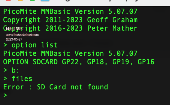
thanks to your help i can set the pins. but i do not succeed to "mount" the sdcard. after option sdcard GP22,GP18,GP19,GP16 option list shows tha right. and i can enter "b:" with no error. now i enter "files". after 1-2 secs i get the message "sd card not found"... is this a problem for many users? i proofed 10x the pins and the cables.  |
||||
| phil99 Guru Joined: 11/02/2018 Location: AustraliaPosts: 2140 |
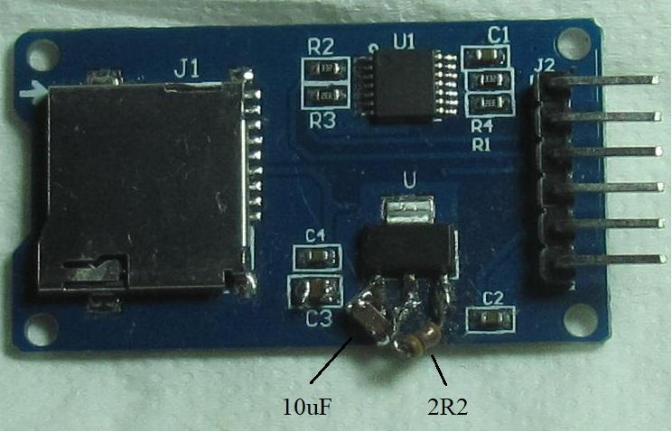
Does that module have a voltage regulator and level shifter chip? If so it is intended for a 5V system. If fed from 5V it will apply 5V to the Pico pins - not recommended. One I have works at 3V3 on a Pico with a 2R2 bypassing the regulator and 10uF added to the regulator output. The level shifter doesn't cause a problem unless SPI is shared with other devices. Edited 2023-05-27 09:21 by phil99 |
||||
| lizby Guru Joined: 17/05/2016 Location: United StatesPosts: 3150 |
What does OPTION LIST show? Can you provide a link to the module? PicoMite, Armmite F4, SensorKits, MMBasic Hardware, Games, etc. on fruitoftheshed |
||||
| hhtg1968 Senior Member Joined: 25/05/2023 Location: GermanyPosts: 123 |
1. thank you for mentioning the 5v. i will proof that. 2. option list shows > option list PicoMite MMBasic Version 5.07.07 OPTION SDCARD GP22, GP18, GP19, GP16 and i can enter "b:" with no error, but "files" leads to "... sd card not found" by the way: and sd card is inserted and formatted...  |
||||
| hhtg1968 Senior Member Joined: 25/05/2023 Location: GermanyPosts: 123 |
to phil99: you are right. i have bought an sd card adapter for 5v! i try to find a solution... many thanks for the help. |
||||
| hhtg1968 Senior Member Joined: 25/05/2023 Location: GermanyPosts: 123 |
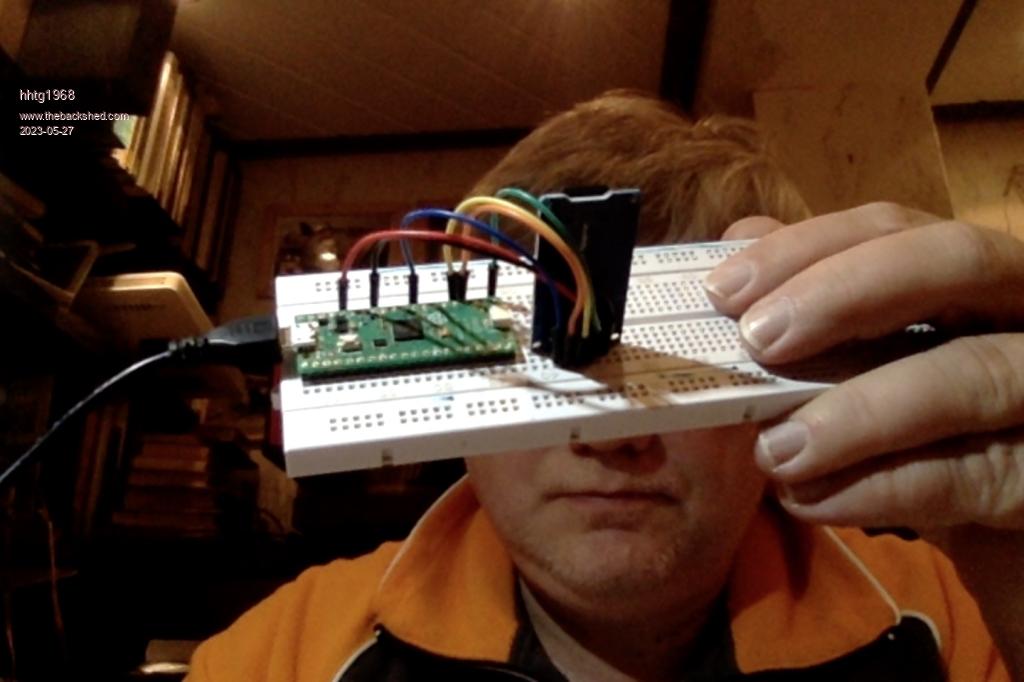
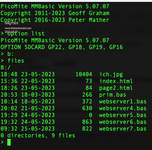
it is easy. thr pico has a pin with 5v!!!!!!! and now it works!!! have a look at the image. do not disturb on the content of the card, that is for a webmite. i only wanted to check the function...  |
||||
| Mixtel90 Guru Joined: 05/10/2019 Location: United KingdomPosts: 6798 |
This style works, I know from experience. It has pullups and a supply capacitor, but it doesn't have series resistors or a voltage regulator. There are other versions. A few voltage regulator versions do work, but they may not work with all sd cards as the voltage may be out of spec. If you are powering the module from 5V you *may* need level shifters on the data lines to avoid puting 5V on the PicoMite pins. Measure the voltage at the PicoMite. If it is 5V then it would be a good idea to try adding 10K pull-down resistors to try to get it to less than 3V6 for safety. Officially the PicoMite will withstand 5V on the pins, but there is no leeway. 5.1V may damage the chip! Edited 2023-05-27 17:09 by Mixtel90 Mick Zilog Inside! nascom.info for Nascom & Gemini Preliminary MMBasic docs & my PCB designs |
||||
| hhtg1968 Senior Member Joined: 25/05/2023 Location: GermanyPosts: 123 |
thank you. but why the pico has a pin (vcc) with 5v if it is dangerous? |
||||
| hhtg1968 Senior Member Joined: 25/05/2023 Location: GermanyPosts: 123 |
another question. i gave this topic a wrong name, "chage" instead of "change". is it possible to change then name? |
||||
| Mixtel90 Guru Joined: 05/10/2019 Location: United KingdomPosts: 6798 |
The 5V pin on the Pico just feeds the on-board switching supply, which steps the voltage down to 3V3. The RP2040 chip itself uses 3V3 and all its GP pins are rated for that. (3V6 is the maximum on any pin according to the specification). Ordinary forum users can't change the thread titles. Don't worry about it - we know what you mean anyway. :) Mick Zilog Inside! nascom.info for Nascom & Gemini Preliminary MMBasic docs & my PCB designs |
||||
| hhtg1968 Senior Member Joined: 25/05/2023 Location: GermanyPosts: 123 |
to mixtel90: what is a "level shifter"? |
||||
| Mixtel90 Guru Joined: 05/10/2019 Location: United KingdomPosts: 6798 |
It's a circuit that converts signals between 3V3 and 5V in our case. Very useful when you want to interface 5V stuff like PS2 keyboards to a 3V3 PicoMite. :) You can make them in several ways, but the one we commonly use is made from a small MOSFET and two resistors. It can be made from discrete components or you can get a module with several of them on it from several sellers on ebay (and similar). This circuit works in both directions - it converts 3V3 to 5V and 5V to 3V3 so it's very useful. Mick Zilog Inside! nascom.info for Nascom & Gemini Preliminary MMBasic docs & my PCB designs |
||||
| hhtg1968 Senior Member Joined: 25/05/2023 Location: GermanyPosts: 123 |
ok and thanx. i orderd two (1.33 euro). |
||||
| Mixtel90 Guru Joined: 05/10/2019 Location: United KingdomPosts: 6798 |
On my current PCB designs, where I'm using a PS2 keyboard, I usually make the level shifter using four resistors and two mosfets. It doesn't save board space, but it allows me to squeeze the circuit in where a module won't fit. Although I have done a design where the level shifter module is underneath the PicoMite. :) Mick Zilog Inside! nascom.info for Nascom & Gemini Preliminary MMBasic docs & my PCB designs |
||||
| phil99 Guru Joined: 11/02/2018 Location: AustraliaPosts: 2140 |
An extra level shifter module isn't needed. Just bypass the 3V3 regulator on the SD module so that it can use the Pico 3V3 supply. The level shifter on the SD module will then be converting 3V3 signals to about 3V3 instead of 5V. This has been tested and proven to work.  The regulator left pin is ground, the middle pin is 3V3 output and right pin is input. If you don't have a suitable resistor and capacitor just replace the resistor with a wire link. (the 'resistor' in the photo is actually an inductor that has a resistance of about two ohms, just using what was in the toy box) Edited 2023-05-28 08:58 by phil99 |
||||
| Page 1 of 2 |
|||||