|

|
Forum Index : Microcontroller and PC projects : port expander
| Page 1 of 2 |
|||||
| Author | Message | ||||
| stanleyella Guru Joined: 25/06/2022 Location: United KingdomPosts: 2129 |
Hi guys. I want to convert an arduino "robot" to picomite but it needs 8 pins for the stepper motors. https://www.ebay.co.uk/itm/174426213588 I tried looking for a device on the forum but no search. Anyone done picomite code for say a 8 channel i2c chip? I'm looking for devices and if any were supported in gcbasic which the robot was coded with. Cheers. |
||||
| Mixtel90 Guru Joined: 05/10/2019 Location: United KingdomPosts: 6803 |
Have you run out of pins on the PicoMite? There is a 16-bit (2off 8-bit ports) I2C port expander, MCP23017. There are none that are *specifically* supported in MMBasic. You need to look at the data sheet and send it the appropriate I2C commands. There will be others. And they will almost all work differently, of course. :) There are stepper motor drivers that go straight onto the I2C bus, but probably only surface mount now. Mick Zilog Inside! nascom.info for Nascom & Gemini Preliminary MMBasic docs & my PCB designs |
||||
| Volhout Guru Joined: 05/03/2018 Location: NetherlandsPosts: 4252 |
Pcf8574 I2c to 8 out or in. But.... Picomite itself has plenty pins. Volhout PicomiteVGA PETSCII ROBOTS |
||||
| stanleyella Guru Joined: 25/06/2022 Location: United KingdomPosts: 2129 |
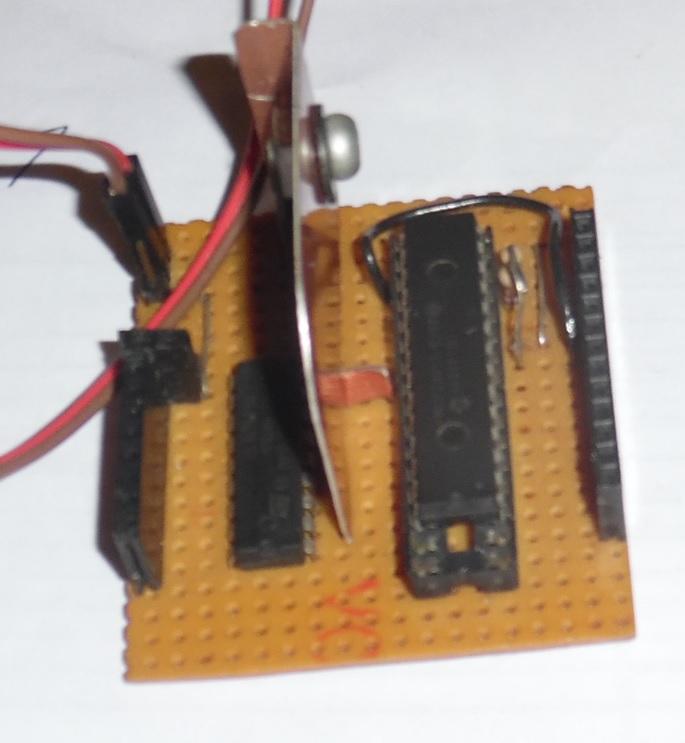
I found a mcp23017 .. which I thought was a pwm expander, doh. It's got a uln driver for 2 4 phase motors. Why did I build it and not use it?? It got i2c pull ups and a 5V reg. I can't find any code I wrote for it.  |
||||
| stanleyella Guru Joined: 25/06/2022 Location: United KingdomPosts: 2129 |
I found another 4 expander chips in a tube and lots of other forgotten stuff. should be easy I2C WRITE addr---0x20 option--0 sendlen--8 senddata--b00110011 a port as output lots to sort but 2 pins for i2c and this will be run at 50Hz interrupt so speed no prob. 328 version https://www.youtube.com/watch?v=s5-5DNa36jk |
||||
| Plasmamac Guru Joined: 31/01/2019 Location: GermanyPosts: 554 |
PCA 9555 D 16-Bit I2C + SMBus I/O-Port, 400 kHz, SO-24 maybe this one Plasma |
||||
| stanleyella Guru Joined: 25/06/2022 Location: United KingdomPosts: 2129 |
mcp23017 .It works as in video, just want to redo in mmbasic... academic ? picomite is cheap enough for a robot and could do an ili9341 animated face with touch and the glcd sdcard for sound. lots of pins and 8 for stepper motors is the reason for the expander. I'll post a solution when sorted. |
||||
| Mixtel90 Guru Joined: 05/10/2019 Location: United KingdomPosts: 6803 |
The 8-bit chip I intended to use for the I2C joystick is the MCP23008, purely because it costs 2.00 UKP from Bitsbox. Mick Zilog Inside! nascom.info for Nascom & Gemini Preliminary MMBasic docs & my PCB designs |
||||
| Volhout Guru Joined: 05/03/2018 Location: NetherlandsPosts: 4252 |
When possible, try to run the I2C bus at 400kHz if you want to drive a stepper motor via a serial connection. The arduino code uses SPI for this purpose, since SPI typically runs faster. The motors aposted have significant gear reducition, so the speed when driven with 50Hz or so is going to be slow. You may need to drive the coils at 200Hz or faster to achieve a speed that you like. You also may want to power the motors through a resistor from a higher voltages (i.e. 12V). Higher voltage allows you to drive the motors (inductive coils) faster. The resistors limit the current so the motor coils don't burn out. Success Volhout P.S. why don't you drive the stepper motors through a serial bus. You might have sufficient IO pins on the pico for parallel control. Much faster (less jitter). Edited 2023-05-10 05:55 by Volhout PicomiteVGA PETSCII ROBOTS |
||||
| Mixtel90 Guru Joined: 05/10/2019 Location: United KingdomPosts: 6803 |
If the distance between the PicoMite and the port expander isn't much then there are SPI versions of the MCP chips (same part number but MCPS). As far as MMBasic goes it's probably just as easy to use those as it is to use I2C. Mick Zilog Inside! nascom.info for Nascom & Gemini Preliminary MMBasic docs & my PCB designs |
||||
| LucV Regular Member Joined: 19/02/2023 Location: NetherlandsPosts: 62 |
Those who are not faint at heart: read on. You are (I think) familiar with the neopixels. A kind of led that is actually 3 leds in one which can be adressed. So a string of neopixels can be programmed that eacht neopixel has a separate color. There is a PicoMite command for that. What on earth does that have to do with port expanding. Well actually everything. You can buy the WS2811 chips without the leds. And without the leds each chip has 3 output ports. That means that by attaching a WS2811 chip to 1 pin of the Pico will bring you 3 output pins. Attaching 2 WS2811 chips to 1 Pico Pin will bring you 6 output pins. So by attaching 10 WS2811 chips you will have 30 extra output pins on your Pico and it will cost you just 1 pin. The only limit is the memory. Even better: Each of the WS2811 outputs can be used as a PWM pin. Is there a drawback ? Yes. You have to be a bir creative by attaching things to the pins as they are common Anode oriented. Does it work ???? Yes actually it works splendid. I have used these with an ATTiny85, ESP01- Wemos D1 Mini, ESP8266 Devkit. I just haven't had it tested with a Pico. But asw Neopixels work with the Pico so should these chips. Cheap, easy to connect, easy to program and like said PWM !!! Examples. I wrote some stories about his using the Old ESP-Basic, Lua and C++ (Arduino lingo) but that should be easy to adapt: Unlimited outputs for your Micro in Basic and Lua Arduino and ATTiny version in C++ controlling a relais Luc Luc's tech Blog |
||||
| Volhout Guru Joined: 05/03/2018 Location: NetherlandsPosts: 4252 |
Nice !!! Must remeber this. Might come in handy one day. I guess the PWM frequency on the WS2811 is totally uncontrolled. So you really need to use it for lighting. Or for a digital IO, drive each pin with 255 or 0. In which case the single pin control is the only advantage (over a I2C device that uses 2). Volhout PicomiteVGA PETSCII ROBOTS |
||||
| Mixtel90 Guru Joined: 05/10/2019 Location: United KingdomPosts: 6803 |
I'll be surprised if you get Stan to use those - they are almost certainly SMD only.  Mick Zilog Inside! nascom.info for Nascom & Gemini Preliminary MMBasic docs & my PCB designs |
||||
| LucV Regular Member Joined: 19/02/2023 Location: NetherlandsPosts: 62 |
Have you looked at the Photo's in my weblog Mick ? No smd but boards to which I soldered wires. Luc's tech Blog |
||||
| Mixtel90 Guru Joined: 05/10/2019 Location: United KingdomPosts: 6803 |
No, I hadn't looked - I'd assumed it was software. Neat little things, aren't they? :) Mick Zilog Inside! nascom.info for Nascom & Gemini Preliminary MMBasic docs & my PCB designs |
||||
| pwillard Senior Member Joined: 07/06/2022 Location: United StatesPosts: 292 |
If you look at the LAND BOARDS GITHUB for the PICOMITE 01 board, you will find examples of how to program the Port Expander IC. picmomite01 The boards are available on Tindie if you actually want one... I really like mine. Tindie Edited 2023-05-10 21:05 by pwillard |
||||
| lizby Guru Joined: 17/05/2016 Location: United StatesPosts: 3151 |
Here is MMBasic test code for MCP23017: ' MCP23017.bas I2C test const mcp23017 = &h20 ' A2, A1, A0, R/W all connected to 0V Const i2caddr=mcp23017 const IODIRA = &h00 ' Port A IO Direction register DEFAULT = I/P const IODIRB = &h01 ' Port B IO Direction register DEFAULT = I/P const IOCON = &h0A ' IO Expander config register - address &h0B accesses same register const GPIOA = &h12 ' Port A General purpose register const GPIOB = &h13 ' Port B General Purpose register const OLATA = &h14 ' Port A latch register const OLATB = &h15 ' Port B latch register const GPUPA = &h0C ' Port C pull-up register const GPUPB = &h0D ' Port B pull-up register ' SetPin 14,I2C0sda ' SetPin 15,I2C0scl SetPin 1,I2C0sda SetPin 2,I2C0scl I2C open 100, 1000 I2C WRITE MCP23017,0,2,IODIRA,0 ' set direction to output I2C WRITE MCP23017,0,2,IODIRB,0 ' set direction to output ' I2C WRITE MCP23017,0,2,GPUPB,&h3f ' set weak pullups on all except bits 6&7 do mcp17 loop sub mcp17 ' I2C WRITE MCP23017,0,2,IODIRA,0 ' set direction to output ' I2C WRITE MCP23017,0,2,IODIRB,0 ' set direction to output print "write to mcp23017 at ";MCP23017 for i = 1 to 6 I2C Write MCP23017,0,2,OLATA,&b10101010 ' I2C Write MCP23017,0,2,OLATB,&b01010101 ' PAUSE 1000 I2C Write MCP23017,0,2,OLATA,&b01010101 ' I2C Write MCP23017,0,2,OLATB,&b10101010 ' PAUSE 1000 Next i I2C Write MCP23017,0,2,OLATA,0 ' turn all off I2C Write MCP23017,0,2,OLATB,0 ' turn all off pause 1000 end sub PicoMite, Armmite F4, SensorKits, MMBasic Hardware, Games, etc. on fruitoftheshed |
||||
| Mixtel90 Guru Joined: 05/10/2019 Location: United KingdomPosts: 6803 |
The best port expander is a Micromite. The second best is another PicoMite. (The Micromite has more analogue ports but less digital. Sometimes you can't win.) Mick Zilog Inside! nascom.info for Nascom & Gemini Preliminary MMBasic docs & my PCB designs |
||||
| stanleyella Guru Joined: 25/06/2022 Location: United KingdomPosts: 2129 |
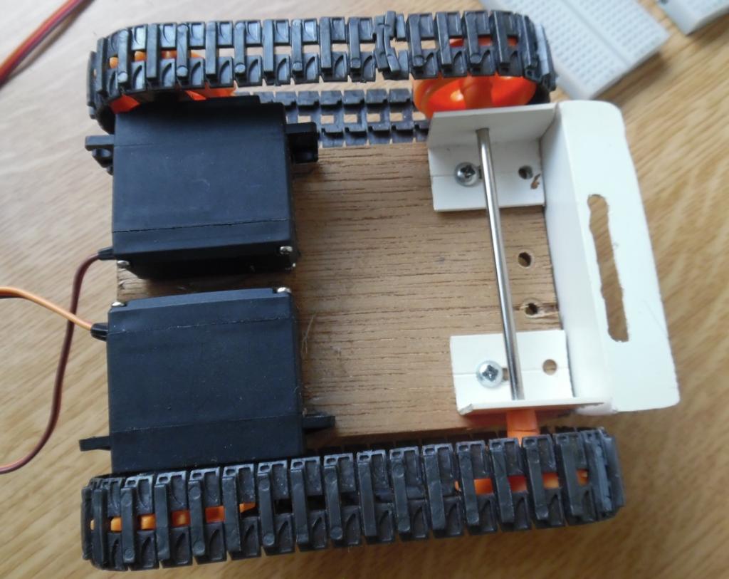
@lizby - Thank you very much for the MCP23017.bas I2C test code, I'll try it in a moment. I have spent time with the data sheet and c code examples but data sheets just confuse me and I don't do c. Asking the forum was not my first option, I'm not lazy, just not bright. I used 328 nano and uno boards only with gcbasic, they're neat boards with usb programming and neater than a pic and pickit... and cheaper. Discovering picomite and mmbasic by seeing a youtube video from "Explaining Computers.com" and now I just use picomite boards. Bit better than 8bit pics. I looked at my "robot" code and it's an every 2mS timer overflow interrupt for the stepper motors and a counter that gives a 50Hz servo refresh, which isn't really needed as the servo is not under load. I found a few abandoned projects when I found the mcp23017 chips, like this chassis that uses servos with the stops taken out for continuous rotation.  |
||||
| Mixtel90 Guru Joined: 05/10/2019 Location: United KingdomPosts: 6803 |
That's rather nice. :) Mick Zilog Inside! nascom.info for Nascom & Gemini Preliminary MMBasic docs & my PCB designs |
||||
| Page 1 of 2 |
|||||