|

|
Forum Index : Microcontroller and PC projects : PicoMiteVGA: Wish List
| Page 1 of 2 |
|||||
| Author | Message | ||||
| Hawk Senior Member Joined: 15/07/2021 Location: AustraliaPosts: 141 |
Thought I'd start a wish list as a place to collect ideas. DEFINE TRANSPARENT <#> <#> - A number from 0 to 15. Default value 0 It would be nice to be able to define which of the 16 colours should be considered the "ALPHA" channel, or transparent channel. This came up fairly soon in my PicoMite VGA programming journey, as I was looking for a way to animate playing cards around the screen. I was considering using SPRITES to move the cards around. Unfortunately, half the cards in a deck are black. Also, in games, many character sprites have a black edge around them, much like a cartoon. With the current implementation that would not be possible. In the meantime, I will look for an alternate solution to my moving card problem. |
||||
| matherp Guru Joined: 11/12/2012 Location: United KingdomPosts: 9129 |
Setting the transparent colour is a big change but what I can do easily is allow all colours including black to be shown. This would be done by adding bit-2 to the options parameter SPRITE SHOW [#]n, x,y, layer [,options] Displays sprite ‘n’ on the screen with the top left at coordinates ‘x’, ‘y’. Sprites will only collide with other sprites on the same layer, layer zero, or with the screen edge. If a sprite is already displayed on the screen then the SPRITE SHOW command acts to move the sprite to the new location. The display background is stored as part of the command and will be replaced when the sprite is hidden or moved further. The parameter ‘options’ is optional and can be set as follows: bit 0 set - mirrored left to right bit 1 set - mirrored top to bottom bit 2 set - black pixels not treated as transparent default is 0 |
||||
| phil99 Guru Joined: 11/02/2018 Location: AustraliaPosts: 2140 |
This issue has been mentioned before. A work-around it to change all the blacks in the sprites to dark green and add a 10k pot in series with the dark green output resistor. When you are using sprites wind the pot up till dark green is almost black. The disadvantage is all colours containing dark green will be off, but you cant have everything. For other programs turn the pot back to zero. |
||||
| Hawk Senior Member Joined: 15/07/2021 Location: AustraliaPosts: 141 |
This is a nice compromise. I put it one the wish list, I didn't anticipate that it'd be easy. I haven't looked at your code at all. It's just a shame that the transparent colour has to be black. If I was able to choose a permanent alternative I'd choose hot pink, but that is likely to upset someone else, and it doesn't have a bit pattern of 0000, presumably the reason that you chose black. I'm sorry if I brought up an old topic. I did search back a fair way looking for discussions, but didn't find any discussions. |
||||
| ice2642 Regular Member Joined: 27/05/2023 Location: BrazilPosts: 82 |
Hello, I am very new with MMBasic, and may English is not very good and maybe some ideas is that I will talk out of scope. Sorry in advance. 1 - Talking in sprites, some way to put it in data or in a some memory space to call it when it is need, like more or less was used with peek poke in commodore 64, creating it with pixels draw in binary data. (Remember, 3 areas with a how when the binary draw or not draw a pixel to form a sprite) This feature will be very cool. 2 - A way to play s3m, mod,XM, mt2, etc... format. Best Regards, MMBasic 5.0707 on PicoMite VGA |
||||
| Mixtel90 Guru Joined: 05/10/2019 Location: United KingdomPosts: 6798 |
Hello & Welcome, Ice2642 :) Memory is very different on the PicoMite to how it works on the Commodore 64 - and different to how it works on lots of others too! The only area where you can always safely use POKE is to POKE into existing variables, which are all cleared by NEW and RUN. There are no general purpose free RAM areas as such. You have to remember that the RP2040 is a microcontroller (more like a PIC chip), not a microprocessor so it's RAM is really designed to be used as scratchpad, with the program running from flash. The CPUs on the RP2040, although fast, are not particularly powerful (and one of them is dedicated to creating the VGA display). RAM is not very big (and is all allocated now), so implementing any sort of music decoding that requires unpacking can be extremely difficult to achieve. This is why mp3 hasn't been implemented. Remember, there is no hardware sound support on the chip at all. Mick Zilog Inside! nascom.info for Nascom & Gemini Preliminary MMBasic docs & my PCB designs |
||||
| Volhout Guru Joined: 05/03/2018 Location: NetherlandsPosts: 4247 |
Hi ice2642, I think the frame buffers can do what you desire. You can paint sprites in them, and copy the sprites to the display layer. As for the audio formats, I think Mick is right. We have WAV and FLAC. You may have to convert your audio to one of these 2. Volhout PicomiteVGA PETSCII ROBOTS |
||||
| stanleyella Guru Joined: 25/06/2022 Location: United KingdomPosts: 2129 |
My 5 cents. If you have a black background the sprites.. or blits don't erase a previous because of black not "written"? so previous post "Setting the transparent colour is a big change but what I can do easily is allow all colours including black to be shown. This would be done by adding bit-2 to the options parameter SPRITE SHOW [#]n, x,y, layer [,options] Displays sprite ‘n’ on the screen with the top left at coordinates ‘x’, ‘y’. Sprites will only collide with other sprites on the same layer, layer zero, or with the screen edge. If a sprite is already displayed on the screen then the SPRITE SHOW command acts to move the sprite to the new location. The display background is stored as part of the command and will be replaced when the sprite is hidden or moved further. The parameter ‘options’ is optional and can be set as follows: bit 0 set - mirrored left to right bit 1 set - mirrored top to bottom bit 2 set - black pixels not treated as transparent default is 0" Is black a colour now that will erase background? |
||||
| Mixtel90 Guru Joined: 05/10/2019 Location: United KingdomPosts: 6798 |
Please don't expect the PicoMite to do sprites like the C64. That had hardware to handle them. The RP2040 doesn't even support LCD text displays in hardware! Everything is done via very clever software and using basic hardware facilities of the chip (a CPU, DMA, interrupts and a PIO). It can never work like a hardware video chip. Mick Zilog Inside! nascom.info for Nascom & Gemini Preliminary MMBasic docs & my PCB designs |
||||
| stanleyella Guru Joined: 25/06/2022 Location: United KingdomPosts: 2129 |
Can amstrad 464 palette switching be done ie draw in colours but set to background then change the colours to show? |
||||
| hhtg1968 Senior Member Joined: 25/05/2023 Location: GermanyPosts: 123 |
do you have an amstrad 464? i have programmed a lot for this machine in basic an machine code. i still program for this machine on a emulator (javaCPC). so i have tons of software... |
||||
| Mixtel90 Guru Joined: 05/10/2019 Location: United KingdomPosts: 6798 |
No. There is no palette to switch. You have 16 colours that are decided by the values of the resistors in the VGA network and that's it. I'm afraid. Mick Zilog Inside! nascom.info for Nascom & Gemini Preliminary MMBasic docs & my PCB designs |
||||
| phil99 Guru Joined: 11/02/2018 Location: AustraliaPosts: 2140 |
Palette switching has to be done with a hardware multi-pole switch (mechanical or electronic, controlled by DOUT pins). Your programs can then then use constants to redefine the colours to match the selected palette. I did something similar to produce RGBI 1111, but 4 bits is 4 bits so it was not worth the effort. |
||||
| Martin H. Guru Joined: 04/06/2022 Location: GermanyPosts: 1114 |
One possible way is in Mode 1, where you can use the TILE command to color or hide foreground and background areas. Using Software-Sprites in the "classical" way might be done with the GUI BITMAP Command. You can define bitmaps for sprite and mask and tie them together with the background using bolian algebra. (just my 2 cent) Edited 2023-06-04 17:35 by Martin H. 'no comment |
||||
| Hawk Senior Member Joined: 15/07/2021 Location: AustraliaPosts: 141 |
I'm interested in the schematic that you used to implement the RGBI. You say that 4 bit is 4 bits, but having access to greys would make pixel art easier imho. I know it has been mentioned that it didn't help with photo transformation, but I'm more interested in pixel art. Do you have a representation of the palette that it produced? Hawk. |
||||
| phil99 Guru Joined: 11/02/2018 Location: AustraliaPosts: 2140 |
Haven't found the schematic yet. It is on the back of an envelope somewhere, will post when found. It used the green low bit for intensity, modulating the other three (so RGIB 1111 really) via transistors. Tried a couple of versions:- 1) With I low R G & B could be 0% or 25% With I high R G & B could be 50% or 100% 2) With I low R G & B could be 0% or 50% With I high R G & B could be 25% or 100% For 4 bit greyscale use a standard R - 2R resistor DAC into an emitter follower driving all three VGA pins. Use constants to assign the RGB values for each grey level. Eg Const Integer Grey0 = RGB(0,0,0) to Const Integer Grey15 = RGB(255,255,255) |
||||
| lizby Guru Joined: 17/05/2016 Location: United StatesPosts: 3150 |
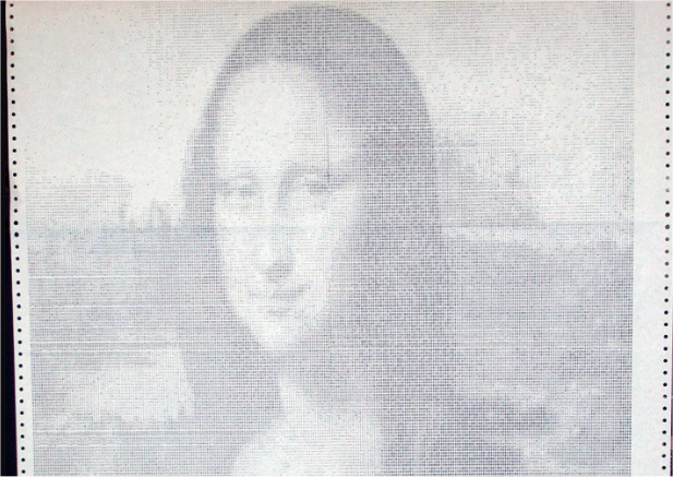
"For 4 bit greyscale use a standard R - 2R resistor DAC into an emitter follower driving all three VGA pins." For those of us who have no idea what a "standard R - 2R resistor DAC into an emitter follower" would look like, can you sketch this out? Thanks for your exploration here. (Thinking back to the days when "computer art" was overprinting on a line printer to get various shades of grey to present the Mona Lisa, circa 1970.)  PicoMite, Armmite F4, SensorKits, MMBasic Hardware, Games, etc. on fruitoftheshed |
||||
| JohnS Guru Joined: 18/11/2011 Location: United KingdomPosts: 3804 |
Forgive a software guy attempt... it's akin to the PicomiteVGA (the emitter thing would be a transistor to boost the signal or combine it or some such and isn't needed in the PMVGA). The R-2R bit means a resistor network to combine the digital outputs (thus DAC - digital to analogue convertor). I think the R 2R means one output goes through R and another through 2R so will contribute half as much to the result. (It's "obvious" that further R values for other colour signals can be used in like manner.) John Edited 2023-06-05 04:43 by JohnS |
||||
| Mixtel90 Guru Joined: 05/10/2019 Location: United KingdomPosts: 6798 |
Here's a typical R-2R network. It's a relatively ssimple DAT. B0-B3 are binary inputs that are driven either low or high. The output is a stepped ramp of, in this case, 16 levels. You can see why it's called a R-2R network. :) The actual values will depend on the application, but the 2R resistors will always be twice the R values. It's important to match the values pretty closely in these networks, especially as the number of stages increases. B0 B1 B2 B3 ! ! ! ! 2K 2K 2K 2K ! ! ! ! +-1K--+--1K--+--1K--+--1K--+---- OUT ! 2K ! GND To use this as a gray scale generator you would probably need a transistor stage fed from OUT to provide enough current to drive the R,G and B video inputs in parallel. Edited 2023-06-05 05:36 by Mixtel90 Mick Zilog Inside! nascom.info for Nascom & Gemini Preliminary MMBasic docs & my PCB designs |
||||
| lizby Guru Joined: 17/05/2016 Location: United StatesPosts: 3150 |
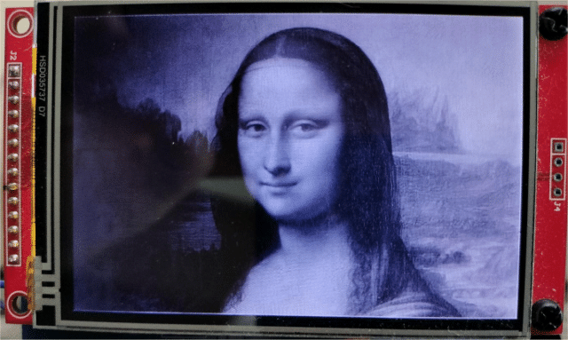
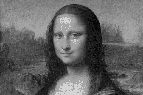
Thanks, John. I'm afraid I would need an actual schematic (sketched out however). Here is a Mona Lisa image I clipped to 3-wide by 2-high, scaled to 480x320 for an ILI9488, and transformed to greyscale with PaintShopPro. PSP reports 218 colors. Here is how the PicoMite presents it:  I think that is pretty good, and the moire patterns shown in the photo aren't evident on the ILI9488. (Actually, the moire patterns I saw on my screen don't show up on the TBS page.) 218 is a lot of grey resolution, so in PSP I reduced it to 16 colors. Not so good looking, but not bad. It would be better if the white were bumped up to the next grey level so the forehead and other highlights weren't white.  How would this compare to PicoMiteVGA greyscale_x_16? ~ Edited 2023-06-05 06:09 by lizby PicoMite, Armmite F4, SensorKits, MMBasic Hardware, Games, etc. on fruitoftheshed |
||||
| Page 1 of 2 |
|||||