|

|
Forum Index : Electronics : Any recommendation for resistance tester?
| Author | Message | ||||
| yahoo2 Guru Joined: 05/04/2011 Location: AustraliaPosts: 1166 |
Some low-life has pinched my old vintage armature testing meter. I am at a bit of a loss as to what I can replace it with. Is there a four wire adapter for a multimeter that will give me an reasonably accurate 0.1 ohm reading? I rang one company and they suggested a new model megger with a low resistance, 40 Ohm range. But they couldn't tell me the margin of error % or how it measured resistance. I'm confused, no wait... maybe I'm not... |
||||
| VK4AYQ Guru Joined: 02/12/2009 Location: AustraliaPosts: 2539 |
Hi Yahoo I used a wire wound pot in series with a amp meter and battery to test armature continuity and consistency if that's what you want. I found this better than just an ohm meter as it loads a bit of current into the windings. http://tech-wonders.blogspot.com/2010/06/measuring-low-resis tance-using-kelvin.html Some where I have a low ohms measurement circuit I will see if I can find it, it uses a Wheatstone bridge bridge as a comparator and from memory it measured down to .1 ohm. Unfortunately I have long lost the actual one I made. All the best Bob Item number: 270713787239 fleabay this is the one I use now OK if good batteries fitted. Foolin Around |
||||
| Warpspeed Guru Joined: 09/08/2007 Location: AustraliaPosts: 4406 |
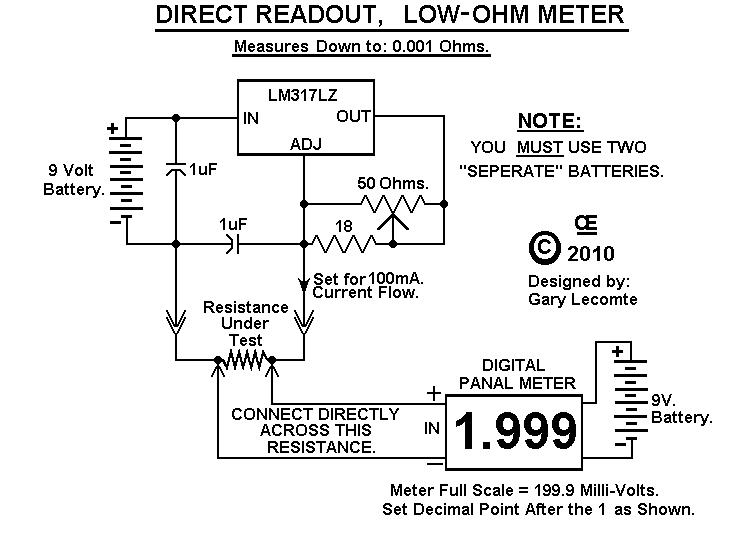
Just had a quick search, and discovered this project: http://electronics-diy.com/electronic_schematic.php?id=951  Cheers, Tony. |
||||
| yahoo2 Guru Joined: 05/04/2011 Location: AustraliaPosts: 1166 |
Thanks fellas, My old "armature tester" originally come from a radio enthusiast so it probably was a proper Milli-ohm meter, I renamed it to avoid arguments with people about why their $20 Digital multimeter couldn't be trusted below 10 Ohms. Saved a lot of time! it had a 100mA and 1A setting and some calibration shunts. Some of my previous home built electronics have been a bit to fragile to stand up to work away from the bench. I probably need to use a better quality of component for this. I see the fluke 289 has a 10 mA 50 ohm range but its pretty pricy! I don't know if 10mA will show up faults like higher currents seem to. I have a couple of spare DC power injectors laying around, I will experiment with them before i make a decision to buy anything. yahoo I'm confused, no wait... maybe I'm not... |
||||
| Warpspeed Guru Joined: 09/08/2007 Location: AustraliaPosts: 4406 |
You are quite right about higher currents needed to more accurately measure very low resistances. The above circuit uses 100 mA, which is going to hit a normal PP9 battery very hard indeed when the unknown resistor is connected up. Why not build the above circuit, but use a one amp plug pack for power ? Provide three constant current outputs available across different output terminals from three separate current regulators, 1 Amp, 100mA and 10mA. The one amp regulator will definitely need a heat sink. Then you will have 0 to 0.2 Ohms, 0 to 2.0 ohms, and 0 to 20 Ohms. Just plug your clip leads into the right holes, and you are set to go. For reading higher resistances than that, an ordinary multimeter should work fine. Thinking about this a bit more, all you really need is the accurate current source. A multimeter on the dc millivolt range can be used to read resistance instead of the panel meter. And a metal enclosure could work as the heat sink. So just a dc plug pack, and a diecast metal box with some 4mm terminals on top may be all you really need. Cheers, Tony. |
||||
| yahoo2 Guru Joined: 05/04/2011 Location: AustraliaPosts: 1166 |
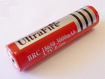
I had exactly the same idea about the multimeter while I was looking at the circuit in your post, it took me by surprise when all the writing disappeared! I will try it with a plug pack for the bench, then build one with 18650 rechargables. I use them in my torches so I have always got them with me, they have plenty of hoot. 
I'm confused, no wait... maybe I'm not... |
||||
| Warpspeed Guru Joined: 09/08/2007 Location: AustraliaPosts: 4406 |
I sometimes do something very similar with my bench power supply. Short the leads together, and set the current limit to give maybe exactly one amp. Run that one Amp current through what I wish to measure, and read the resistance directly with a digital multimeter. Having a "magic box" that can fairly accurately source a range of reference currents would be a lot more convenient, but I don't really do a lot of very low resistance measurement, at least not enough to build something up specially. Cheers, Tony. |
||||
| larny Guru Joined: 31/10/2011 Location: AustraliaPosts: 346 |
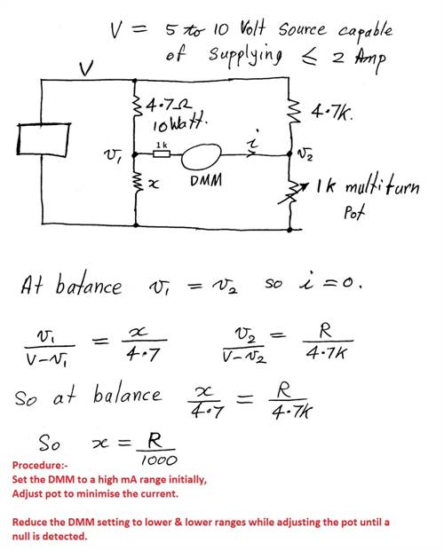
Here is an idea. Make a simple Wheatstone Bridge. You could use a multiturn pot with a multiturn calibrated knob. Or simply, balance the bridge, open one end of the pot & measure its resistance with the DMM. Len Edit. I have replaced the diagram with a modified one. I inserted a 1 k resistor in series with the DMM. This is to limit the current to a safe value in case x is high or open & the pot is, by chance, near the low resistance end of its range. 
|
||||