|

|
Forum Index : Electronics : Working out RMS on 3 phase
| Author | Message | ||||
| Gizmo Admin Group Joined: 05/06/2004 Location: AustraliaPosts: 5078 |
Quick question for the electronic guru's. RMS for single phase is 0.707 of the peak voltage. What I need to know is how to work out the RMS for 3 phase and 7 phase. Thanks in advance Glenn The best time to plant a tree was twenty years ago, the second best time is right now. JAQ |
||||
| KiwiJohn Guru Joined: 01/12/2005 Location: New ZealandPosts: 691 |
I am probably sticking my neck out here but as far as I can see RMS is 0.707 for a sine wave and will be the same for 1, 3 or many sine waves (ie phases) you are blending together. |
||||
| Gizmo Admin Group Joined: 05/06/2004 Location: AustraliaPosts: 5078 |
You could be right, but I just have this feeling its different for the number of phases. Maybe I'm looking for the wrong answer. RMS from memory is the equivalent working DC voltage to a AC voltage. If we feed 10vac into a load and it uses 10 watts, then 7.07 vdc would also give 10 watts into the same load. But if we feed 10 vac 3 phase into a load to produce 10 watts what would be the dc voltage, I have a feeling it would be higher. Maybe I'm heading down the wrong path. Trying to find the relationship between the number of phases and power, to prove why 3 phase is better than 1 phase, or 7 phase is better than 3 phase. Glenn The best time to plant a tree was twenty years ago, the second best time is right now. JAQ |
||||
| KiwiJohn Guru Joined: 01/12/2005 Location: New ZealandPosts: 691 |
I think you understanding of RMS is about right. I dont think more phases mean more power, just power in a more convenient form especially if you want a rotating magnetic field an electric motor and some advantages regarding the size of line conductors. |
||||
| Chipboy Newbie Joined: 13/12/2006 Location: AustraliaPosts: 16 |
RMS voltage is relevant to an individual phase, the number of phases is not relevant. They would each have an RMS voltage each as Gizmo described above. Sorry I did not answer your direct question regarding RMS on 3 phase system between phases. On 3 phase its 1.73 * Vphase. A seven phase system is another kettle of fish but suffice this rule does not apply to anything other than 3 phase. eg on a 240 volt system, 240 * 1.73 = 415Vac, but I point out this is between phases. The RMS of each individual phase is as you suggest 1/sqrt2 = 0.707 Matt Wind wannabe |
||||
| Gizmo Admin Group Joined: 05/06/2004 Location: AustraliaPosts: 5078 |
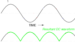
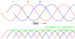
OK, I've worked out what I should be asking. Average output. A single phase AC source rectified with a full wave bridge has a output that reaches the peak voltage, and drops down to zero. A 3 phase AC source with full wave rectification would have the same peak voltage, but not drop to zero. It has a higher average output, and therefore more power. I doctored a couple of images I found on the net to explain the single and 3 phases. 

So I need to calculate the average output on single, 3 phase and 7 phase. Glenn The best time to plant a tree was twenty years ago, the second best time is right now. JAQ |
||||
| Chipboy Newbie Joined: 13/12/2006 Location: AustraliaPosts: 16 |
Not sure I want to go back to the maths required for a 3 phase system (uni was 20 years ago) but on a seven phase system suffice to say the average voltage (Vrms) will be very close to Vpeak. As you can see on a 3 phase full wave rectified output (as you've shown) it won't be too far off. A heck of a lot higher than 0.707 of one phase! Get some heavy duty (20 or 30Amp) schottky rectifier diodes from computer PSU (the better models have larger ones for the high current 5V line, take a look they are substantially bigger than the 12V line) and go for it (far lower loss). Marvelous diagrams though, I am impressed. Matt Wind wannabe |
||||
| RossW Guru Joined: 25/02/2006 Location: AustraliaPosts: 495 |
1 phase is 360 (electrical) degrees, or 180 peak-to-peak when fullwave rectified. 90 degrees from 0 to maximum, half-way (average) 45 degrees. cos(45) = 0.7071 3 phase is 120 (electrical) degrees, "peaks" every 60 degrees therefore, so the lowest point of intersection every 30 degrees, or 0.866 7 phase is 51 (electrical) degrees, peaks every 25 degrees, lowest point of intersection 0.976 I may have the wrong terms here, but I think the numbers should be right. Be interesting to see some empirical testing. |
||||
| brucedownunder2 Guru Joined: 14/09/2005 Location: AustraliaPosts: 1548 |
I guess it's still going to be a trade-off in a way. I put the retifier block together and considering the extra diodes ,the block being up at the mill ,and the lossey dc feed to the battery box ,(if this is a long length). With the new model Stator, we might have to hone up our skills on actually re -winding the poles. I've thought of a way using bobbins that may be able to be removed from old stators . Wind them and slide them over the pole steel, I think ?. Use carefully removed wire from old Stators-you won't need as much as we now only have 36 poles. ( By the way ,did those guys have any luck with the Neo conversions discussed lately ? as I still think from my conversion that there's a lot more power to be extracted using Neo's-could be wrong!!.) Mine just sits there doing nothing <compared to the F&P rotor , but when it does get a move on ,the rise in O/P is very steep. Sorry to get off track a bit -- Bruce Bushboy |
||||
| KiwiJohn Guru Joined: 01/12/2005 Location: New ZealandPosts: 691 |
Ummm.. as far as I know the average voltage of any number of identical phases will be the same as the average voltage of any one of those phases? 
If you are connecting rectifiers between neutral and phase lines the rectified voltage will be the RMS value of one phase, the power output of the machine will be this voltage multiplied by the number of phases and the total current of all phases being paralelled. If you are connecting rectifiers between phase lines the voltage will be higher and will depend upon the angle between the two phases. The voltage will always be less than twice the voltage of one phase except if there were an even number of phases in which case the voltage between 180 seperated phases would be twice the single phase voltage. I believe that adding any number of identical sine waves will produce a sine wave the magnitude of which depends upon the angle of phase between the sine waves. When opposite sine waves (i.e. phase difference of 180 degerees) are added a zero output is produced. The diagrams I drew in the 21 phase topic helped me to understand this, maybe I missed something?  |
||||
Robert_VK2BBR Regular Member Joined: 31/12/2006 Location: AustraliaPosts: 67 |
when dealing with 3 pase ac it was always worked out as cube root of voltage of single phase. Therefore 1.73 X single phase. as in 240 and 415. maybe that would also apply to seven phases, 2.64 times the single phase voltage. I dont know what asuptions were made concening phase angle. Robert 1555 W grid connect system since Jan 08 both vehicles running on modified, used vege oil. |
||||
| Megawatt Man Senior Member Joined: 03/05/2006 Location: AustraliaPosts: 119 |
G'day Gizmo, Where angels fear to tread..... I reckon what you're after is the DC output voltage of the rectified AC voltage. For a single phase full wave bridge setup, with the input voltage Erms,the DC voltage out is 0.9*Erms. The rms value of the rectified AC is still 0.707*Epeak, because as you have observed yourself, the instantaneous value of voltage drops to zero after the first half cycle. It's just a normal sin wave with the second half turned up-side-down. If you have a three phase bridge, the output voltage instantaneous value never dives to the zero axis because, again as you have noted, at 0.866 the next phase takes over so the voltage rises again, yielding a higher average voltage, so you can expect both the average and rms values to be higher. And they are. The DC voltage is 2.34*Erms and so is Erms. Because the difference between the voltage level of the bottom pointy bits of the waveform and the top smooth sin wave peaks is not much, there's bugger-all difference between the DC and rms votages. If you have a three phase centre-tap connection, DC voltage is 1.35*Erms and so is the rms voltage, again because the differences between high and low points of the ripple is small. For a 7 phase centre tap connection, I haven't done the calc, but as you point out, at 0.976, the next phase takes over from the previous one and the difference between top and bottom of the ripple are even less. So the average or DC voltage will be about 99% of the peak value, or pretty close to 1.4*Erms. Almost square root 2 and that's because if there were no ripple the DC voltage would be 1.414*Erms. And out of left field, yes, I now would like to know the inductive reactance of various poles on stators. Also from same place in the field, Mr F&P has indicated that he did not want to tell me the saturation flux density for his steel. Commercial in confidence, fair enough, still worth an ask! Megawatt Man |
||||