
|

|
Forum Index : Electronics : NEW POWER LOGGER DESIGN
| Page 1 of 2 |
|||||
| Author | Message | ||||
Downwind Guru Joined: 09/09/2009 Location: AustraliaPosts: 2333 |
The Power Logger 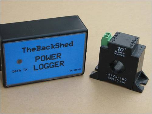
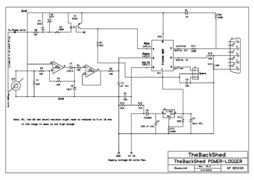
The circuit has gone through many changes over time since I started this project. It has also reduced in the component count as well as increased in reliability This is the circuit I have settled on, and has worked reliable with a range of different windmills, from 12 to 48 volt. It can also be used to log the power consumption of a house AC mains power or inverter output. As it was designed to be used mainly with a windmill, this article will cover windmill use. The logger circuit will read data from the windmill system and export the data to a computer where it can be recorded and able to be viewed. It will work with Glennís PicLog software and Gordonís Windmill Analyzer software. All calibration of the readings are done in the computer software on screen, but will need actual meter readings to preform the calibration within the software. The logger will read battery Voltage, Amps generated by the mill that is feed to the battery, and RPM of the mill. Watts and Watt/Hours is calculated from the data and also recorded on the computer. There is a spare Input/Output (I/O) left on the board for use with another sensor like and anemometer etc. to record wind speed. The circuit itself is very simple and should allow for the lesser skilled in electronics to be able to construct it easily. It consists of 3 main input sections, Volts, Amps and RPM. The volts is a simple voltage divider consisting of 2 resistors, a 2K2 resistor to ground and a 27K resistor on the positive input from the battery, this combination should allow for a input voltage anywhere up to 60 volts to be monitored. The Amps is derived from the use of a Current Transformer (CT) placed on One of the AC phase wires from the mill and located before the rectifier. The CT allows for the circuit to be electrically isolated from the high current going to the battery. The two terminals on the CT are wired back to the 2 input terminals provided on the circuit board. A on board shunt resistor across the CT input reduces the voltage and gives a loading to the CT. The input signal is feed through a dual Op-amp where it is conditioned and filtered to give a linear output proportional to the current from the mill. RPM is taken from 1 phase wire and feed through a Darlington Opto-coupler to square the input wave and to control the gain of the signal to below 5 volts. Any excess voltage on the input is limited by a zener diode. All 3 conditioned outputs are then passed to a Picaxe 08m chip where the A to D conversion and pulse count is done, before outputting the data to the computer via a serial port or a Serial to USB cable. The circuit is powered by 5 volts via a high voltage regulator on the board (TL-783) this will handle up to 125 volt input but the 330uF input filter capacitor is only rated to 63 volts. This sets the maximum allowable input voltage to 63 volts or less. I will offer a complete kit form of the logger for a limited time, for anyone that is unable to make a circuit board or construct their own from the information given below. The 08m chip will be supplied pre programmed in the kit for ease of use. Please PM me if you would like this in a complete kit form. All information, circuit artwork, parts list, picaxe source code, etc, can be downloaded from the files at the bottom of this article. A circuit layout for the components and a schematic can also be printed from the files below. 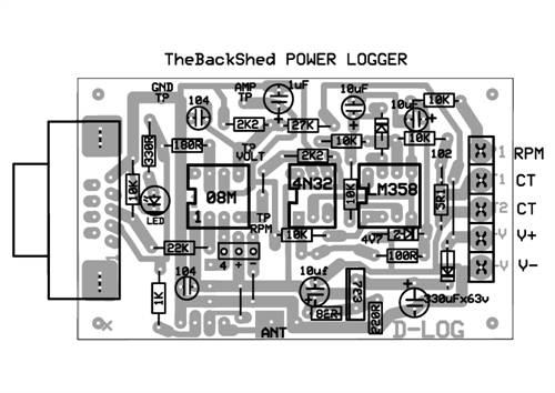
Circuit Assembly Start with fitting the 3 Ic sockets to the board and ensure the notch is facing towards the com port socket end of the board. Solder in place. 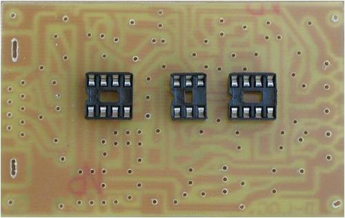
Next fit the diodes and the wire links, take care the diodes are orientated the correct way and each is in the right location. The zener diode is marked with the red circle The wire links are made from 4 cut off legs from other components after soldering. You might need to fit a couple of resistors first before you have some cut off legs to work with 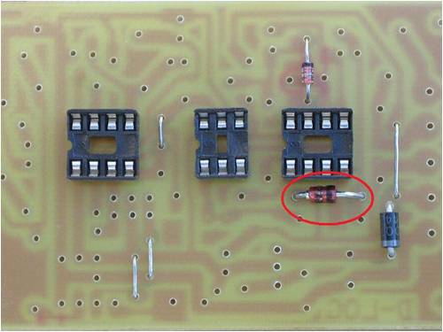
Fit the 6 x 10K resistors next. 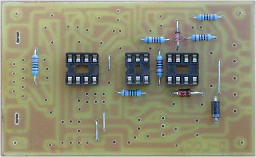
Fit the remaining resistors to the board. Note the 2 at the bottom are vertical mounted 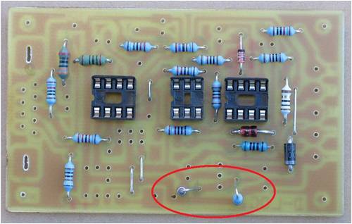
Then the capacitors, taking care the electrolytic capacitors are orientated the correct way on the board. 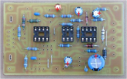
Install the voltage reg and all other remaining components 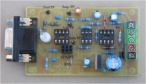
The test point pins can be left off the board if you choose, as without a cro to view the signals with they are not much use. Ensure the led is correctly orientated with the flat side facing to the bottom of the picture. It is best to interlock the 2 terminal blocks halves before inserting them into the board. You will need to ensure all component legs are trimmed short or there will be problems fitting it in the box. The unused holes to the bottom of the picture are for a 433mhz wireless transmitter should you choose to require it. (not provided) There is also previsions made for a pull up or pull down resistor to be fitted to the spare in/out pin. The kit will be supplied with a white header connection for the spare I/O like this, as the board pictured above was constructed to accommodate a sister board as a special request. The board will except either style socket or pins. Pins for 5V+ and negative is also allowed for. 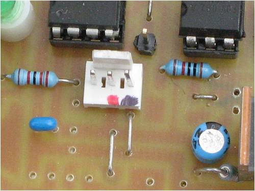
A pre cut out box will supplied in the kits to fit the board into. 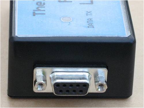
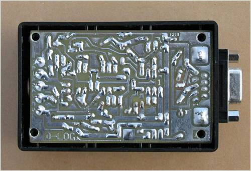
A usb to serial cable will also be supplied for connection to the PC 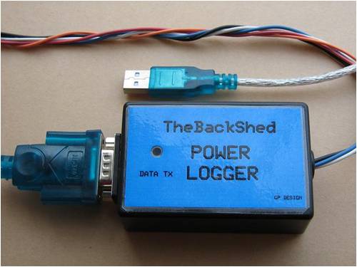
A CT is included in the kit. 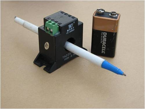
Wiring schematic of the CT 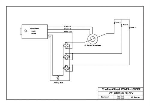
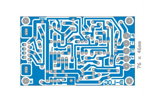
Circuit Artwork PDF 2010-06-23_010950_Circuit_artwork.pdf Circuit Artwork PCBExpress 2010-06-23_011209_Circuit_artwork_PCBExpress.zip Component layout PDF 2010-06-23_011311_Component_overlay.pdf Schematic PDF 2010-07-05_192216_POWER_LOGGER_SCHEMATIC.pdf CT wiring schematic PDF 2010-06-23_011357_Wiring_Schematic.pdf Parts list PDF 2010-06-23_011604_LOGGER_PARTS_LIST.pdf Picaxe source code PDF 2010-06-23_011647_Source_code.pdf Picaxe Source Code Zip 2010-06-23_011827_Source_code.zip Ebay supplier for CT. CT LINK I have tested a few different Current Transformer and even though nearly all gave a workable output, the basic block style that is supplied in the kit, was found to be the best with readings from well below an amp up to the maximum I was able to test to. It also gave less jitter to the readings and a better linear output. For those who do not wish to disconnect power wires to place the CT on the phase wire, a cheap AC tong tester designed for a add on to a multimeter can be used, this way the CT just clamps around the wire. I donít think the accuracy is anywhere as good as the fixed CT but it should work. 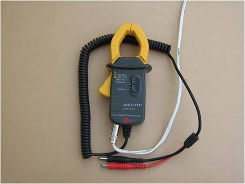
One of a few tested (from Jaycar ) worked ok but needed over 200 watts of current draw before it gave any voltage out. It also needed to be modified inside the tong itself. Inside there is a small simple little circuit board, that has some resistors and a trimpot that are directly across the CT outputs. These are not needed for use with the logger board, as the circuit has already got this in it, and is tuned to suit the circuit. I cut the track on the pcb inside the tong tester and added a small earphone socket to mine When the earphone plug was inserted it disconnects the resistors on the output and connected the CT output direct to the earphone plug. This allows for the tong tester to be used with a multimeter as intended or with the logger. 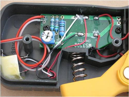
It is a very easy modification to do. Or you could just snip the resistors off the board inside the tong tester and use the wires on the curly cord supplied. 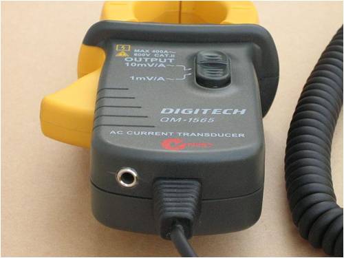
I also tried a cheap $10.00 AC tong meter from China that I feel was a better buy than the one above. This also needed to me modified with a earphone jack fitted. This was a very easy task and just required 1 wire being soldered to the new plug and a pair of wires added to loop back to the circuit board as shown below with the addition of the white wire and 1 black wire. 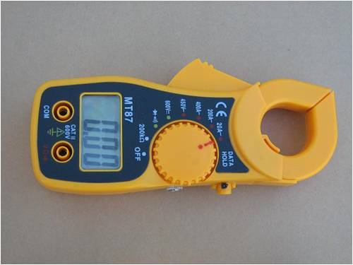
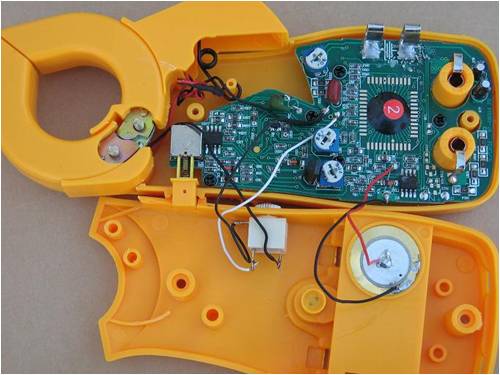
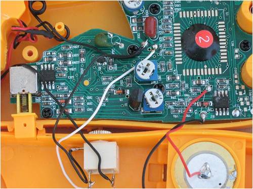
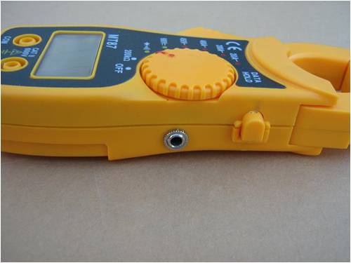
I give very much Thanks to Gordon for and the many hours of testing he has done and the effort he has applied to the development of his software package to complement this circuit design. I also Thank Glenn for himself sharing his initial work with PicLog, as without it both Gordon and myself would not have developed this package for all to use. This has been a joint effort with Gordon doing the software and myself doing the circuitry with interjection from both sides of the fence, into each others part of the project, This I believe has made for a better overall complete system and given greater simplicity to its construction and software use, with many benefits. Kit Information Before anyone jump down my neck on trying to profit from my work, I would like to point out all information is supplied here for those who wish to produce there own, and there is little profit made from the kits. I would much rather each produce their own if able, but offer a kit for those who can not. The kit will include all components required, including a pre drilled circuit board, an enclosure cut out to fit the board, a CT, A usb to serial cable including the driver suitable for XP, Vista, Win 7, (not sure for 64 bit) Required by you is to assemble the board and solder the components in place. No connecting wiring is included. This kit do not include a wireless transmitter even though the board has provisions for one. All thoughts, ideas, views and criticism welcome. Pete. Sometimes it just works |
||||
| Gizmo Admin Group Joined: 05/06/2004 Location: AustraliaPosts: 5078 |
My comment.... WOW! Glenn The best time to plant a tree was twenty years ago, the second best time is right now. JAQ |
||||
| Janne Senior Member Joined: 20/06/2008 Location: FinlandPosts: 121 |
Pete, Nice build and well documented. Offering it as a kit should make data acquisition much easier those incapable (or too busy to) of building such a thing. I'm not so sure if the current transformer is the best choice to measure the current, but considering the ease of install and relative low cost I think it should be the best overall compromise. Personally, I'd like something to measure on the DC side, shunt or a hall-effect sensor. Many thanks for sharing this.  If at first you don't succeed, try again. My projects |
||||
Downwind Guru Joined: 09/09/2009 Location: AustraliaPosts: 2333 |
Thanks Janne, The Ct has the advantage of not needing to connect into heavy battery wiring, but will agree it has limitations if you dont have access to the AC phase wiring. The advantage with the Ct is, it can monitor any AC current regardless if its the mill or inverter or whatever and not voltage effected. I am currently testing some dedicated shunt monitoring chips that allow for up to 80 volt input with 0 to 5 volt output suitable for high side monitoring. This could be added to the spare I/O for shunt monitoring of solar or mill. The problem is they are a SMD package and not easy to source. What is the range of amps you need to monitor and at what voltage. Pete. Sometimes it just works |
||||
| VK4AYQ Guru Joined: 02/12/2009 Location: AustraliaPosts: 2539 |
Hi Pete Top job mate well worth waiting for and the construction explanation is simple enough for me to follow but I may get the odd resister in backwoods. All the best Bob Foolin Around |
||||
| hoggie Newbie Joined: 11/06/2010 Location: Posts: 8 |
Hi Pete Great job!! I want one. Steve |
||||
| KarlJ Guru Joined: 19/05/2008 Location: AustraliaPosts: 1178 |
OK Pete send me 50 kits thanks. bloody awesome ps i dont really need 50 kits but I bet you jumped!! Luck favours the well prepared |
||||
Downwind Guru Joined: 09/09/2009 Location: AustraliaPosts: 2333 |
Hi Karl, As soon as the 12 gold bars arrive the kits will be in the post. 
Pete. Sometimes it just works |
||||
AMACK Senior Member Joined: 31/05/2009 Location: AustraliaPosts: 184 |
Pete, What make and model Wireless transmitter can be used on the Circuit? And where Can I get one. I need a project for that bread board I have thrown under the bench.  *Note to self 1. Make it thick 2.Make it heavy. 3.Make it stronger than it should be. 4. Don't rush the first job as the second job will cost more and take mor |
||||
Downwind Guru Joined: 09/09/2009 Location: AustraliaPosts: 2333 |
Hi Amack, The 433mhz modules from Jaycar will fit the board. (ZW-3100 & ZW-3102) pp.82. As Hoggie pointed out to me earlier the Jaycar TX units are 3 volt rated so you would need to replace the wire link on the board for the V+ to the TX with a 220 ohm resistor. You will need a second picaxe (08m) on the bread board receiver.(you proberly have that along with the bread board) Bread board will keep you know and wont go off. 
Pete. Sometimes it just works |
||||
| SSW_squall Senior Member Joined: 20/03/2010 Location: AustraliaPosts: 111 |
HI Pete, Just a few comments on the new logger design: Looks good generally but there are a couple of things that stick out: Namely the opamp, that precision rectifies the AC output from the CT for the PICAXE. It isn't exactley clear where the LM358 opamp power supply is obtained from, from the PCB layout it look like it's connectted between 5v and gnd. Given that the LM358 is NOT a special type of opamp with rail to rail inputs this doesn't look good, because the opamp can't work properly when it's inputs are with in 0.3v of EITHER supply rail. When the output from the CT goes negative the volatage will just be caught by the clamp diode (inside the IC) on the inverting input, depriving the opamp of the opportunity to move it's output in the positive direction. The unity gain buffer will not to well either when the input is not between 0.3v and 4.7v Ovbiously you've got this working in some fashion, otherwise you wouldn't have put up the design, i am supried that it does through! Two options(to keep thing constructive): 1. Reference the CT to half the supply voltage (2.5v). This is possible but will halve the resolution, zero current being half scale on the ADC, because the ADC in the PICAXE is referenced to gnd. 2. Use a negative supply for the opamp. This is preferable and not too hard to achieve. To generate a negative supply there a couple of possible ways: 1. Capacitively couple the phase output of the wind turbine to drive a half wave rectifier to generate a negative voltage, then regulate this with a 4.7v zener. The negative volatge would only be present when the AC was, but no AC and there's nothing to log anyway But the cacpacitor would have to be suitably rate for use with mains or inverter AC voltages, even then it would be unsafe and unreliable. 2.a Use the spare output on the PICAXE to generate a squarewave, then use this to drive a negative facing diode through a capacitor. Actually you'd probably want to go with a voltage doubling charge pump here to ensure some voltage overhead. Then filter and regulate with a 4.7v zener. 2.b Use a 555 timer IC to generate the square wave (and keep your spare input) then do as above. This negative supply voltage will then keep the opamp happy, allow it to rectify and buffer the CT output voltage properly. The other thing that would be good to see would be some clamp diodes going to the 5+ on the ADC inputs of the PICAXE to ensure that they don't get subjected to overvoltage. Happy to sketch out these thought as a circuit diagram, so you can see what i'm talking about... Best regards AB Einstein: Everything should be made as simple as possible, but not one bit simpler |
||||
Downwind Guru Joined: 09/09/2009 Location: AustraliaPosts: 2333 |
Hi AB, Thanks for your comments. The opamp will work down to zero but is limited to 3.5 volts on the high side (Vcc-1.5) It is suitable for single rail supply. [code]INTERNALLY FREQUENCY COMPENSATED LARGE DC VOLTAGE GAIN: 100dB WIDE BANDWIDTH (unity gain): 1.1MHz(temperature compensated) VERY LOW SUPPLY CURRENT/OP (500žA) ESSENTIALLY INDEPENDENT OF SUPPLY VOLTAGE LOW INPUT BIAS CURRENT: 20nA (temperature compensated) LOW INPUT OFFSET VOLTAGE: 2mV LOW INPUT OFFSET CURRENT: 2nA INPUT COMMON-MODE VOLTAGE RANGE INCLUDES GROUND DIFFERENTIAL INPUT VOLTAGE RANGE EQUAL TO THE POWER SUPPLY VOLTAGE LARGE OUTPUT VOLTAGE SWING 0V TO(Vcc - 1.5V) DESCRIPTION These circuits consist of two independent, high gain, internally frequency compensated which were designed specifically to operate from a single power supply over a wide range of voltages. The low power supply drain is independent of the magnitude of the power supply voltage. Application areas include transducer amplifiers, dc gain blocks and all the conventional op-amp circuits which now can be more easily implemented in single power supply systems. For example, these circuits can be directly supplied with the standard +5V which is used in logic systems and will easily provide the required interface electronics without requiring any additional power supply. In the linear mode the input common-mode voltage range includes ground and the output voltage can also swing to ground, even though operated from only a single power supply voltage.[/code] I dont care if it wont reach 5 volt output and work between 0 and 3.5 volt to the adc input. I could have added a second v-reg and supplied the opamp with a slightly higher voltage to offset the 1.5 volt drop. If you read the data sheet for the picaxe you will find it has internal clamp diodes on the adc inputs, so seen little point in adding a extra diodes, and considering the only adc input that can go higher than 5 volt is the one reading the voltage should the input voltage exceed 60 volts. As the current is limited by the resistors in the voltage divider there should be no problem with the internal clamp diodes handling the over voltage. Secondly the 330uF cap on the voltage input rated to 63 volts will likely distroy itself if more than 60 volts is exceeded. One of the main limits i set when designing the circuit was to use easy to find components that could be accessed world wide. It dose put some limits on the operation but little point in using components that no one can find. The other limit i had was to keep it simple where possiable, to keep it in the reach of a constructor with limited electronic knowledge. I have always maintained it is not the best circuit that i could have created but find no purpose in complicating it so much no one will have the understanding to build it. As simple as this circuit is many will find it challenging enough as they dont all have the skill level that youself and a few others do. I would be happy if you care to design out a better circuit for us all to see. Many have claimed to have great ideas, but other than Glenn no one has got off their ass and bothered to put a complete logger circuit to the forum. Pete. Sometimes it just works |
||||
| GWatPE Senior Member Joined: 01/09/2006 Location: AustraliaPosts: 2127 |
Hi Pete, The finished article looks as good as the draft. My test unit can resolve down to 0.1A, so this is good enough I think. The cct has come a long way since your first question to me re measuring AC current. The issue SSW_squall raised re opAmps rectifying the very low AC signals is difficult to comprehend, as we are using a normal diode to rectify with. The ccts do work though. I have been a bit busy recently working through a PLC C-code program that was engineer designed from manufacturers data sheets. It did not work. I had to work it back to simple steps, and heh presto it now works. What I am saying is that sometimes the KISS principle is best even though it may not seem technically correct. This cct gives an alternative current measurement logging system for a windmill, and I am sure many will appreciate the benefits of not requiring series connections to heavy wiring. Well Done with the article. Gordon. become more energy aware |
||||
oztules Guru Joined: 26/07/2007 Location: AustraliaPosts: 1686 |
Pete, Thanks for a very nice article. It is so well documented that anyone with a will can emulate it. You have also offered it as a kit, and I commend you for doing this dual effort. It is exactly what I feel is needed for a DYI site. Those who can will, those who cant have options. Let me be clear, I have no problem with making a kit available. I have no problem with what ever price you think is fair for your supplying the parts.... and I have no problem with you becomming a dozen-air or even a millionair with the proceeds. You have done what I would think is the very best of both worlds, and offered a tested solution for those wanting this kind of device. They can build it and get whatever macabre pleasure DIYers get doing this stuff, or they can avail themselves of your efforts and buy it. It does not get better than that. Ghurd would be proud of it, Glen should be proud of it being on his site, and I am happy to reference this article to anyone..... any time. I acknowledge the comments by others re: the opamp, but it appears that in testing it has done the job. As you well know, any circuit is never perfect, and any circuit board layout is always capable of improvements......a thicker track here, a better bend to clear a component by more there... etc... it never ends. But if it works as described, you can ask for no more. I know we always don't see exactly eye to eye..... but.... Well done indeed. ..............oztules ps I confess to using the same sort of CT in a lot of pwm applications. It can have some shortcomings, but all seem to be able to be overcome.... and we get isolation as a bonus. I don't mind opto iso isolators either sometimes... but Kiss is a damn good system too..... sometimes it just works  (to quote a bloke I know) (to quote a bloke I know)Village idiot...or... just another hack out of his depth |
||||
Downwind Guru Joined: 09/09/2009 Location: AustraliaPosts: 2333 |
Hi Oz, Thanks for the kind words of encouragement. I realize the op-amp will always be a limiting factor, but as you say what do you do and where do you stop with a circuit. I did try a CT from a psu but got lots of strange jitter in the ac down low that i was unhappy with, all a bit strange so i discarded the idea of being able to use one here effectively. Also not everyone has a shed full of junk like some of us. 
Any ideas on how best one could be used, as it would be good to recycle an old psu bits if able for the home builder rather than source a new CT. Must admit i havent tried one lately with the current redesigned circuit. As for seeing eye to eye ...well that will always be difficult, because you are shorter than me. 
Pete. Sometimes it just works |
||||
oztules Guru Joined: 26/07/2007 Location: AustraliaPosts: 1686 |
hmmm.... I suspect that the frequency may have been too low in the lower current (read RPM as well). The psu item will likely have been ferrite, perhaps use a little 5w mains transformer, and put in a single turn around the windings for your current wire (may have to ditch the secondary if space is limited) and use the 240v primary as the ct drive. Hopefully the soft iron will carry the low frequencies better. Did this happen more with the 12 pole axfx designs, or the F&P units. If the axfx was the downfall, then the frequency problem (ferrite) will likely have been the case, as the F&P would have a higher frequency in the low amp range than the axfx units..... or put another way, the noise would overpower the signal as the attenuation became high for the lower frequencies. If this helps, then any old wall wart will be a fair sacrifice/recycle victim. Maybe.... maybe not? .............oztules Looking for high platform shoes ... or a short step ladder  Village idiot...or... just another hack out of his depth |
||||
Downwind Guru Joined: 09/09/2009 Location: AustraliaPosts: 2333 |
Oz' It was back when i first started this project i tried the psu ct, so all's a little foggy now, but it was on a F&P i tried it with. I had tried a few things like inductors etc and found they worked with a few wraps of the phase wire, but found that they didnt give a linear output like the bought ct did. I havent tried a mains transformer. Will do when i get a spare moment from becoming a dozen-aire. Pete. Ps:- a couple paint can stilts should about do it. Ahhr.... makes me think of when i was a kid and we had no internet, so the things we done to kill time back then...........the good old bad days.... Sometimes it just works |
||||
oztules Guru Joined: 26/07/2007 Location: AustraliaPosts: 1686 |
Keep in mind, you don't want to saturate the core. Your F is low, not the 40khz in the psu For decent linearity (v/amp against primary current ) 1. Keep the leakage to a minimum perhaps toroidal will help here. 2. Minimum primary inductance wants to be one where the inductive reactance will be about 100 times the primary AC impedance at F min. 3. We don't want a saturated core.... so lots of secondary, and a decent cross section of core for the frequency expected. In simpler terms...... try different cores with different cross sections, and find one reasonably linear...... Or, grab a tranny, and bang a single primary turn on it or possibly a wire through it (toroidal)to keep saturation away, with a resistor on the secondary=30R) or so, and test for linearity, and saturation. This will give a fair idea of the core required. If your keen try this Everything is simple in theory, but not always in practice (well mostly) ............oztules Village idiot...or... just another hack out of his depth |
||||
Downwind Guru Joined: 09/09/2009 Location: AustraliaPosts: 2333 |
For those who have a PicLog circuit board and would like to adapt either the CT circuit or the RPM circuit to be used with their own PicLog board here is a Vero board break down of the 2 circuits. There is a PDF file attached that can be printed out for a clearer view of the circuit layout and for the CT schematic. 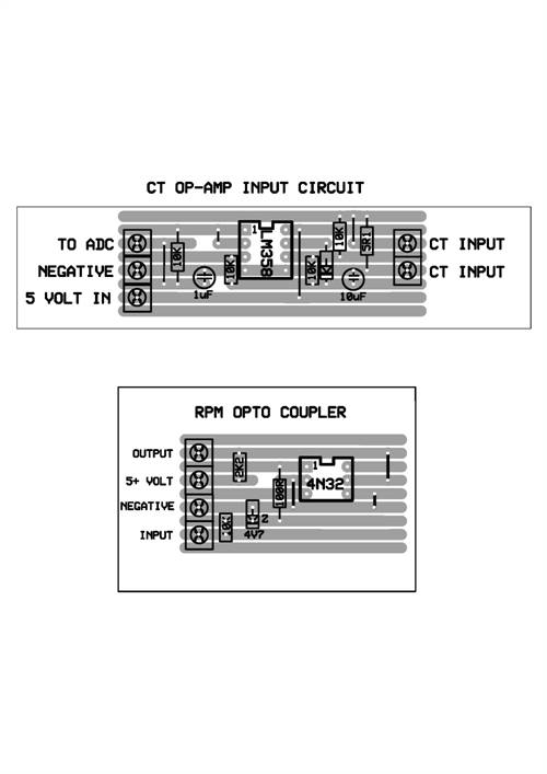
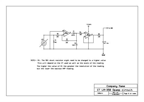
2010-06-25_151336_CT_LM-358_OpAmp_circuit_schematic.pdf 2010-06-25_152037_Vero_Board_RPM_and_CT_Circuits.pdf Pete. Sometimes it just works |
||||
| SSW_squall Senior Member Joined: 20/03/2010 Location: AustraliaPosts: 111 |
Hi Pete and others, Please belive that i'm not out to ruffle feathers, here some more suggestions that are a little more concrete: I was thinking today you might also want to leave the RPM optocoupler uncommitted. In other words not tied to GND, such that you could wire it directly across one the phases in either star or delta. Because tieing it to GND pre-supposes that the AC voltage generated by the phase wire will be symmetrical and this may not always be the case. It could also be affected other things if itís sharing the same ground with power being generated. Back on to the main game, here's the suggested circuit that builds on the basic current transformer interface design, which I think is still fairly simple: Overview: Current transformer Ė> adjustable gain stage Ė> improved precision half wave rectifier Ė> time constant filter Ė> protection diode -> PICAXE ADC 2010-06-26_010527_CT_interface.pdf Starting with the current transformer specs: Max current: 160A (RMS I assume) Ratio 1000:1 Recommended load: 50 Ohm Output current: 0-160mA Hence the CT delivers 50mV per amp into the 50 Ohm load Given that 160A RMS full scale is probably more than we need for a RE system, letís aim for 40A RMS full scale into the PICAXEís ADC. Giving 0.05 x 40 = 2V RMS at full scale. This allows for max resolution of the measured current The first stage is an basic inverting amplifier, this allows some voltage gain (or voltage attenuation for other different CTís) to be applied to the incoming signal. This also allows for some adjustment or calibration of the sensed current. 2v RMS is 2.83 V peak. The peak voltage is important because the peak voltage swing is limited by the power supply to the opamp. The simple charge pump circuit driven by a square wave supplies about (negative) -4V to the opamp. Using the PWM generator in the PICAXE to put out a 10kHz square wave of about 50% duty cycle will work fine supplying 1-2mA that the opamp needs. The rectifier diodes are common 1N4148 fast signal types which can better deal with the high frequency output. Alternatively a 555 timer IC could be used to generate this square wave signal. The positive supply is obviously +5V the same as for the PICAXE As the output from the CT goes positive the output of the first amplifying stage will go negative. This is important because this limits the maximum voltage that can be sensed. Conveniently the 2.83V peak allows some(1v) margin for error which keeps the output away from the supply rails. The adjustable gain is given by Rpot / R3 in this case about maximum of 3.7x Of course changing the ratio of these resistors will allow for different CTís to be accommodated and also different full scale currents. Making R3 bigger than Rpot will mean the incoming voltage can be attenuated or reduced: eg 0.5x or 0.2x I will refer to Rod Elliotís excellent application note on precision rectifierís, as to the benefits of this circuit. Rod elliot's app note on precision rectifiers Note that it is an inverting amplifier again so it sense the negative voltage making it only positive. But for the sake of an extra diode and small 1nF capacitor, itís more accurate at low levels and is less inclined to oscillate and cause problems. The time constant formed by the R8 4.7k and C2 10uF capacitor averages the voltage so it can be sampled by the PICAXEís ADC. The full scale output will be around 3v which keeps us away from the positive supply rail by a comfortable margin. If the opamp was powered off a higher voltage than the PICAXE than we could use 100% of the range of the ADC at the cost of an extra power supply regulator. But 3/5 = 60% is not too bad (As you rightly pointed out) There is no need to buffer voltage this as the ADC does not draw any significant current and wonít drag down the voltage being measured. We could PROBABLY get away without the protection diode because the opamp is powered off the same supply voltage as the PICAXE. But Iíve included it because itís good design practice. Re opamps: This picture of the opamp internals explains why it needs a negative supply voltage, the green line show the signal path. 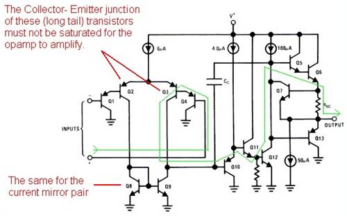
The long-tail common emitter input stage, needs to have some reasonable voltage across the collector - emitter junction for the transistor to vary itís collector current in accordance with the input signal (voltage). If the input transistors are saturated or close to being saturated they canít operate properly. At an input voltage of zero volts there is barely 0.7v across each transistor, since we are concerned with amplifying small voltages accurately, this is NOT good design practice. RE protection diodes: The internal clamp diodes inside any PIC are the last line defence against destruction and problems. It is unwise to rely on them for protection, in practice they should NEVER conduct any significant current (ie greater 0.2mA). Hence it is strongly recommended to use a 100 ohm resistor with clamp diodes between GND and V+ when any analogue input is taken off board or connected to a higher voltage source. The 100 ohm will have a negligible effect on the voltage the ADC is sampling in normal use. But will ensure that external diode holds the over-voltage down and only a current equal to the difference between the forward biased voltage of the external and internal diode divided by the 100 Ohm resistor flows. Limiting this current will protect the PIC. By the way this is not just theory: I had this issue with the sub amp Iíve designed. The auto sense turn on circuit applies a gain of about 220x to the incoming audio signal which is then precision half wave rectified by the exact same circuit with a 4.7k resistor and 10uF time constant cap. Because the gain has to be quite high to sense a small signal of about a 5mV for turning the amp on, the circuit would as a consequence saturate (over-voltage) the ADC input when reasonable signals of greater than about 0.15v were applied. Without a protection diode to V+ this would fairly reliably lockup and crash the PIC. So even through they donít do anything 99% of the time, they need to be there for the other 1% to stop things stuffing up!! Anyway i hope these comments are taken in the way there intended Regards AB Einstein: Everything should be made as simple as possible, but not one bit simpler |
||||
| Page 1 of 2 |
|||||