|

|
Forum Index : Electronics : Temu Induction Heater
| Author | Message | ||||
Bryan1 Guru Joined: 22/02/2006 Location: AustraliaPosts: 1343 |
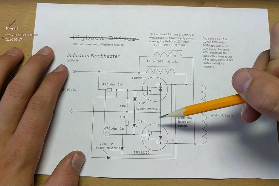
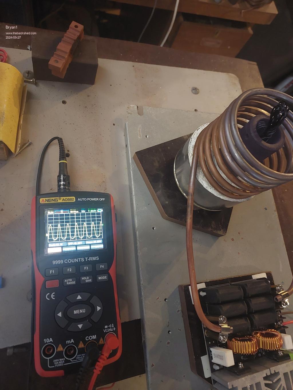
G'day Guy's, Well I got this Temu induction heater for $49 just to have a play,  Now the supplied coil was under 40mm internal diameter and just too small so I first made a 4" diameter coil then changed it to a 3" diameter coil. Now the supplied coil was under 40mm internal diameter and just too small so I first made a 4" diameter coil then changed it to a 3" diameter coil.I used a an old machining project as the crucible and found it only get to around 460C and stays there. Did some quick research and soon found the circuit so upgrading this is going to be needed. Now with crucible in it was drawing around 340 watts and I do think we need to get around 1Kw to get the crucible over 1000C to melt copper. This is the circuit and I do have a heap of HY5608 fets and looking at those small chokes from the aerosharp they are 0.5 mH for the caps ordered 20 of those to use as the cap bank.  Here is a pic of the setup  I have found any metal below the coil so I cast some refractory cement into a tin can and with this morning trial the tin is heating up so I'll take the can off and just have the refractory block. So the heatsink issue can be fixed. I did look at this many years ago and guy's were doing the same thing as the ZVS oscillator is the electric version of a small forge. Regards Bryan |
||||
| phil99 Guru Joined: 11/02/2018 Location: AustraliaPosts: 2134 |
Insulating the crucible may be all you need to do. Cast a refractory cement cylinder to fit between the coil and the crucible. Make formers from thin cardboard or stiff paper wrapped loosely around the crucible and inside the coil. Mix the cement with plenty of sawdust. When the sawdust burns out it leaves voids that improve the insulation. As you have already observed keep it well away from metal when running by sitting it on a brick or cement block. When trying to melt wire rather than a solid lump you may need to improve the RF coupling by winding it into a multi layer coil with the turns parallel to the drive coil, and the ends twisted together. . Edited 2024-09-27 14:24 by phil99 |
||||
Bryan1 Guru Joined: 22/02/2006 Location: AustraliaPosts: 1343 |
Hi Phil thanks for that tip on insulating the crucible and I did find a Coopers Lager beer can was just the right size for a former so the refractory cement cast is done. I just put a 5/8" nut under the crucible to raise it and tomorrow when it's done I'll peel off the can and get the crucible out. Also I put some sawdust in as per your suggestion and I found a brick the right height to sit under the coil. I did try everything I know to get that 20x4 LCD working on that RP2040 Zero but everytime it came back with the error of the LCD not open did my head in so a change of tack was needed. I was surprised just how quick those RP2040camera boards got processed and they have shipped already. Now I do have 1.5Kg of tin coated copper from an old job I did where I kept the billets from punching holes in an ironworker so I'll have to come up with an idea for a bronze project when this unit does it's job. Regards Bryan |
||||
Bryan1 Guru Joined: 22/02/2006 Location: AustraliaPosts: 1343 |
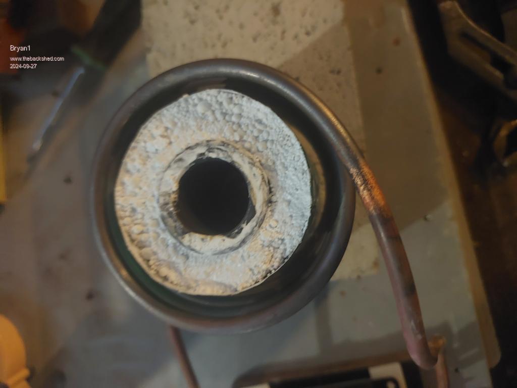
As I had a couple of powdered iron toroids here decided to wind 35 turns of 1.6mm and found out it was 12mH so kept unwinding turns and ended getting down to 5 turns for 232uH so going 3 inhand for 5 turns should get me around 70uH and shouldn't get too hot when in use. Now silly me ordered 0.47uf caps instead of 0.047uf so I reckon 10 in series in 2 strings will get down to around 0.47uf.  There's a pic of the cast in the coil and it fits in nicely with plenty of headroom so I'll give it another run in the morning after I get the cast stripped. Regards Bryan |
||||
| phil99 Guru Joined: 11/02/2018 Location: AustraliaPosts: 2134 |
Page 41 of the current manual lists which LCDs work with MMBasic. Paste the bits of your program that setup / use the LCD here, or on the Micro controllers page (more LCD experts will see it there). Edited 2024-09-27 18:00 by phil99 |
||||
Bryan1 Guru Joined: 22/02/2006 Location: AustraliaPosts: 1343 |
Hi Phil I did use those exact lines of code, now I did the DEVICE LCD INIT on the commandline and when I made a simple program where I just used the DEVICE LCD 1, 2, "sleeping" came up with the error Not in Use. Now after I did a reflash trying to do that LCD init came back with the error GP1 isn't a input so moved everything one pin over only to find GP2 isn't a input went all the way to to GP10 and it still wouldn't work. When I first setup the text did appear and trying a DEVICE LCD CLEAR came back with not Open error. After that nothing worked so I did think time for a break. I did do a post on this on my SSD1963 thread but it's gone unanswered. Now numerous times you have put up that tweak you use for searching this forum but silly me has never written it down. The search function on this forum for me just doesnt work |
||||
| phil99 Guru Joined: 11/02/2018 Location: AustraliaPosts: 2134 |
In your browser search bar type:- site: thebackshed.com "your search terms" The quotes are optional, but they seem to make the search more specific. |
||||
Bryan1 Guru Joined: 22/02/2006 Location: AustraliaPosts: 1343 |
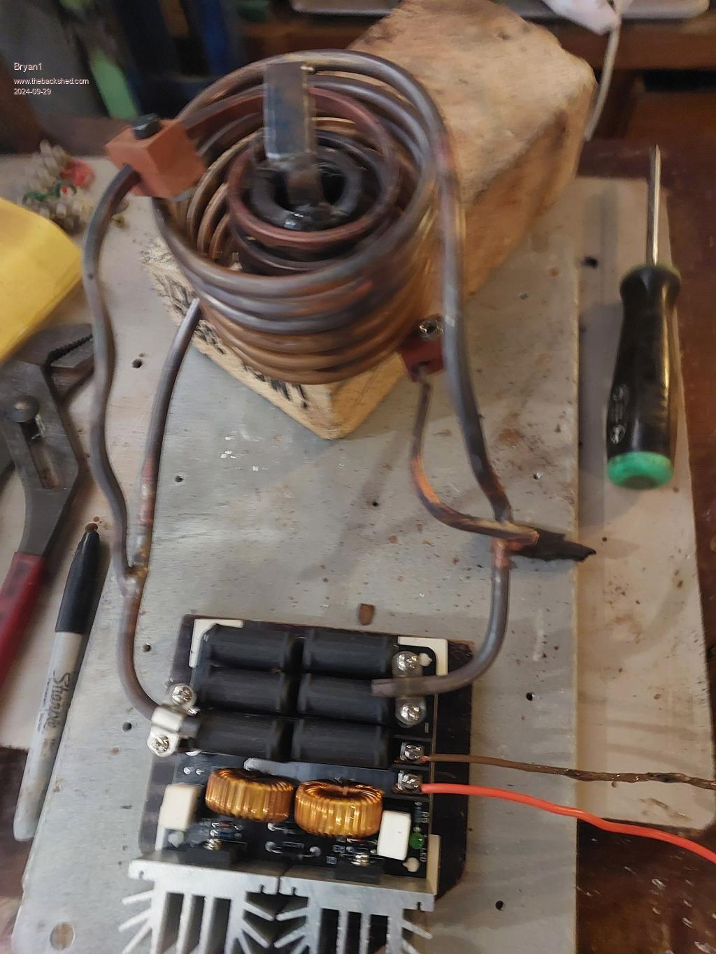
G'Day Guy's, Well took Phils suggestion and made another coil to sit inside the copper coil. Silver brazed the connections and gave it a run.  Well the 15 amp fuse popped so put a 30 amp fuse and that one popped so put another 30 amp fuse and used my clamp meter and 64 amps was being drawn. The 30 amp fuse soon popped so found a 63 amp fuse  Not thinking on the size of the wire about 5 minutes into the run lets just say the cable let out the magic smoke and lots of it Not thinking on the size of the wire about 5 minutes into the run lets just say the cable let out the magic smoke and lots of it  So cut the negative wire coming from my shed battery and looks like I'm going to have to move it closer to the battery due to the current drawn. So cut the negative wire coming from my shed battery and looks like I'm going to have to move it closer to the battery due to the current drawn.I welded on a handle so the crucible can placed and removed easily. Now with these duel coils I'm thinking it may be too much for this Temu board so when I get back from holidays I can on making the new heavier duty one. Regards Bryan |
||||
| phil99 Guru Joined: 11/02/2018 Location: AustraliaPosts: 2134 |
It seems I failed to explain properly what I meant. I the photo the copper you wanted to melt in the crucible was bunched up vertically. That will absorb the RF energy poorly, So wind it into a coil (with the ends shorted) that just fits in the crucible with the turns parallel to the RF coil. Having two RF coils in parallel is obviously overloading the oscillator. Put the refractory cement insulator you made between the crucible and the original coil. |
||||